|
The Model Body Corporation was a small
Detroit-based body
manufacturer that specialized in the production of sample automobile
bodies for
Detroit automobile manufacturers who couldn’t afford to have their own
prototyping
departments. They provided services similar to those provided by
Creative
Industries and ASC in more recent times.
The creative force behind the operation was
George J. Mercer (b. Feb., 1869-d. Nov. 23, 1952), one of the most
talented body engineers an designers
of his day.
George John Mercer was born in England in
February of 1869
to George and Emily (Newman) Mercer. In
1876 the Mercer family emigrated to the United States, locating in
Eastern
Pennsylvania where young George was attended the local schools. He was
apprenticed to a carriage builder who sent him to New York City to
attend the CBNA’s
(Carriage Builder’s National Association) Technical School for Carriage
Draftsmen and Mechanics, graduating in 1893.
He worked for a number of years as a
draftsman and designer
in several of Manhattan’s largest shops, becoming well acquainted with
Jacob H.
Klein, The Hub’s resident technical editor / carriage designer /
draftsman. Published
from 1858-1919, ‘The Hub’ was the nation’s earliest and longest running
monthly
trade publication for carriage builders. It was succeeded by ‘The
Automotive
Manufacturer’ in 1919.
George J. Mercer and Annie Alma Cowper were
married in
Manhattan on October 27, 1897, their marriage certificate lists
George’s
parents as George and Emily (Newman) Mercer; Alma’s as Fred L. and
Flora
(Donyles) Cowper. The 1900 US Census lists the couple at 439 West 99th
Street,21st Ward, Borough of Manhattan, his birthdate
February, 1869 in Pennsylvania, his occupation, carriage maker. Alma’s
birthdate is
given as September 1866, in England, her emigration year as 1886.
Most of Mercer’s employers are currently
undocumented,
however it is known that he served as chief body designer for the H.H.
Franklin
Manufacturing Company, of Syracuse, N.Y., from 1905-1908. The December
1907 issue of The Hub included the
following tidbit:
“Carriage Draftsman Honored
“George J. Mercer, a draftsman favorably
known to the
carriage trade, but for the last two years chief body designer for the
H.H.
Franklin Manufacturing Company, of Syracuse, N.Y., will sail on
December 14th
for London, Eng., his native home. Mr. Mercer is on vacation and
shortly before
leaving Syracuse he was surprised by about seventy-five of his friends
and
fellow-employees, who presented him with a solid gold watch in
remembrance of
the esteem in which he was held. Mr. Mercer will, upon his return,
continue in
the service of the well-known automobile manufacturers.”
Mercer resigned from Franklin in 1909 to
form his own body
design studio in partnership with his old friend Jacob H. Klein - his
position
at Franklin being assumed by William H. Emond (whose biography is also
included
on this site). The 1910 US Census lists Mercer’s home address as 442 W.
180th
Street, Manhattan as follows:
“George J. Mercer (b.1875, immigrated from
England in 1876),
his wife Alma, (b. 1872, immigrated from England in 1890) his
occupation,
designer of automobiles"
The two friends (Jacob H. Klein and George
J. Mercer) were
both graduates of the CBNA’s (Carriage Builder’s National Association)
Technical School for Carriage Draftsmen and Mechanics, and were active
in its Alumni
Association which was formed in 1904. At that time the Alumni
Association’s
officers included: Andrew F. Johnson, president; Walter C. Yelton,
vice-president; Jacob H. Klein, secretary and treasurer, and
George J. Mercer, historian.
To the best of my knowledge Klein &
Mercer was the
nation’s first free-lance automotive design firm. The pair’s Columbus
Circle
office was located in the heart of New York’s automobile row at 1777
Broadway,
New York, NY, one block north of A.T. Demarest’s new 9-story
manufactory.
Mercer’s partner, Jacob H. Klein, was born
in Weehawken,
Union Township, Hudson County, New Jersey, in May 1870 to Matthias (b.
in
Germany) and Elisabeth (b. in Switzerland) Klein. He was named after
his uncle,
Jacob Klein, who worked as a blacksmith and introduced him to the
carriage
trade.
The 1870 US Census taken June 21st, 1870 – states
he was 1/12 months old at the time. His father, Matthias, 34-yo born in
Prussia, was a grocer, and his mother Elizabeth, 23-yo was born in
Switzerland
Living in the same house was his uncle Jacob
(28-yo, b. in Prussia), a blacksmith, his aunt Joan (24-yo, born in New
Jersey) and
their daughter Anna M. Klein, 2-yo, born in New Jersey.
The 1900 US Census lists Jacob H. Klein’s
home address as
1020 Eleventh Street, Hoboken, Hudson County, New Jersey, his
occupation,
draughtsman. States he was born in New Jersey in May, 1870 to two
German
immigrants, as was his wife Elizabeth (b. May 1872). The couple had two
children; Raymond L.(b.1900) and Marie E. Klein (b.1905) and their
listing in
the 1930 US Census lists their home address as 1124 5th
Ave., North
Bergen, Hudson County, New Jersey with Jacob’s listed occupation as
draftsman,
automobile bodies.
The July 7, 1909 issue of the Horseless Age
contained a
brief item on the new firm:
“Klein & Mercer have established
themselves as expert
body draftsmen at 1777 Broadway and will prepare drawings for
automobile bodies
for both commercial and pleasure vehicles.”
Both partners had spent many years honing
their skills in
the drafting departments of Manhattan’s finest carriage builders, and
were
occasional guest lecturers at Andrew F. Johnson’s carriage drafting
classes.
Klein & Mercer’s central location put
them in walking
distance of most of Manhattan’s high class automobile distributors. The
pair
could meet with a prospective client at the distributor’s showroom and
have a
sketch ready within 24 hours. Upon approval, the required body drafts
would
then be completed within a couple of days, after which they would be
delivered
to a metropolitan New York coachbuilder of the customer’s choosing.
Klein & Mercer were not the only
freelance body designers
in Manhattan at that time. George W. Cole, George P. Harvey, Leon Rubay
and J.
Franklin deCausse offered similar services during the teens, which
ultimately
led to the establishment of the world-famous LeBaron Carrossiers in
1920.
After a number of years, Klein left the
partnership, which
was continued by his junior partner, George J. Mercer. The sign on his
door
read ‘Automobile Body Architecture’, and he advertised his services in
the
leading trades of the day. One listing from 1916 follows:
“Body Designers
“GEORGE J. MERCER - Body Designer and
Draughtsman. Special
Designs and Shop Drawings of Pleasure and Commercial Automobile Bodies.
1789
BROADWAY, New York, NY.”
Mercer remained in Manhattan until 1918 when
he relocated to
Detroit to become a consultant for the Saxon Motor Car Company. Mercer
continued to freelance, and maintained a separate office in the
Stormfeltz-Lovely Bldg, 7310 Woodward Ave. at Grand Boulevard, Detroit.
When he
wasn’t busy designing automobile bodies, Mercer spent his spare time
writing
about them.
Between 1910 and 1942 Mercer published well
over 1,000
articles in the nation’s automotive trade magazines, and wrote 3
definitive
technical books; Motor Body Engineering (1928), Motor Body Designing
Problems
(1931), and Motor Body Blue Print Technology (1933). He was a frequent
contributor to The Automobile (aka Automotive Industries), SAE Journal,
Autobody, Autobody Trimmer & Painter, Autobody & the
Conditioned Car,
Automobile Trade Journal, Motor Body, Paint and Trim, etc.
Mercer joined the Society of Automotive
Engineers in 1915
and was active in the organization for the next three decades, many of
which
were spent as head of the SAE’s Standards Committee. He also kept in
touch with
his former friends from the CBNA’s Technical School, as a director of
the
Andrew F. Johnson Society (aka The Johnson Club), and served as
president of
the Alumni Association of the Technical School for Automobile Body
Designers
and Engineers.
In addition to his automotive body work,
Mercer ventured
into other automotive-related activities and designed a brake testing
machine
for the Bendix-Cowdry Brake Testing Company in 1933.
After his retirement in 1942, Mercer was
instrumental in
acquiring Andrew F. Johnson’s massive reference library for the Detroit
Public
Library’s Automotive History Collection. Also included was
Mercer’s
personal collection of manuscripts, letters, photographs, engineering
drawings,
etc., of carriages, automobiles, trucks and other vehicles.
The 1920 US Census lists him at 42 Winder
St., (b. 1870 in Pennsylvania)
district 6, Detroit, Wayne County, Michigan, occupation Automobile
Designer.
While Mercer continues to be well-known as a
body engineer,
he should also be given credit for helping to found the nation’s first
prototype and experimental coachwork facility, the Model Body
Corporation.
Founded in 1919 with a capitalization of
$60,000 by Gustav L. Gast, Andrew Sauter, G. Lester French,
and George J. Mercer, the
Model Body Corp. was located in a small shop at 3261 Bellevue Ave.,
Detroit,
Michigan. The firm’s officer were as follows Gustav L. Gast, pres.;
Andrew
Sauter, vice-president; G. Lester French, treasurer,
and George J. Mercer, secretary and general manager. The
firm’s
listing in the 1920-22 Detroit Directory follows:
“Model Body Corp. – 3261 Bellevue av. Inc. ’19,
Cap. $60,000. G.L. Gast, Pres.;
Andrew Sutton*, V-Pres; C. Lester French, Sec-Treas.”
(* should be Andrew Sauter)
Gustav Louis Gast (b.1868 in Germany,
emigrated in 1888) was
president of the Detroit Furniture Mfg. Co., 803-809 Bellevue Ave.,
Detroit
(1903 directory lists him as V-Pres. and general mgr. of same.)
Like Mercer, Andrew Sauter (b.1885 in
Germany emigrated in
1909), was a well-known automobile body builder, engineer and draftsman
(1920
US Census, body builder, auto factory)(1930 US Census Body Engineer,
auto
factory) ( 1940 Census, draftsman, auto plant).
The firm’s secretary-treasurer, Charles
Lester French
(b.1895 in Detroit), had no experience in the field, his expertise was
accountancy,
and prior to founding Model Body Corp., he occupied a position as
bookkeeper in
the Dime Savings Bank. His father, George S. French was vice-president
of the Houghton
& French Ice & Coal Company, Detroit.
A biography of French includes a mention of
Model Body
Corp.:
“This company does its own designing and
makes open and
enclosed bodies, sample bodies, and also hoods. The bodies contain
trays and
other automobile equipment and the firm has already established a high
reputation for its model bodies.”
In 1922 the Model Body Corp. was
recapitalized (to $110,000)
and relocated to a much larger facility at 7201 Six Mile Rd., which
allowed
them to produce small runs of special bodies if requested, the May 1922
issue
of issue of The Automobile (Automotive Industries) reporting:
“Model Body Increases Its Capital to
$110,000
“DETROIT, May 1 — The Model Body Corp.
has increased its
capital stock to $110,000, and is issuing $50,000 in cumulative 7
per cent
preferred stock at $40, which will be non-redeemable and fully
participating
with the $60,000 common stock. The company will double its present
factory space
and make several important additions. Model Body has been specializing
in
custom body work, ambulance bodies and bus work, but is planning to
undertake
production for several important passenger car companies. The
officers of
the company are G.L. Gast, president; Andrew Sauter, vice-president; G.
Lester
French, treasurer, and George J. Mercer, secretary and
general
manager.
The firm’s entry in the 1923-24 Detroit
Directories being:
“Model Body Corp. – 7201 Six Mile Rd. E.
Inc. ’19, Cap.
$110,000. Claude B. Talbot, Pres.; G.L. Gast, V-Pres.; C. Lester
French,
Treas.”
Claude B. Talbot (b.1886 in New York) was
prominent in the
Detroit lumber business, owning the C.B. Talbot Trustee Co., a large
wholesale
lumber house. He was also involved in finance serving as Pres. of the
Standard
Discount Corp. and V-pres., Peoples Mortgage Corp.
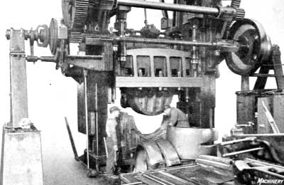
As the firm specialized in the production of
sample
automobile bodies for Detroit automobile manufacturers very few of
their
projects were discussed in the trades, one notable exception being a
flexible
closed body system developed by Kenneth L. Childs.
For a number of year Childs was the
Manhattan representative
of the Standard Textile Products Co., a Youngstown, Ohio holding
company that
operated oil cloth mills in Akron, O., Newark, N.J., Athenia, N.J.,
Montrose,
N.Y., Astoria, L.I., Norristown, Pa., Columbus, Ga, and Mobile, Al.
Apparently Childs had been experimenting
with fabric-covered
bodies in his spare time, first with California-topped touring cars in
1919
then later with closed coachwork. Childs believed that fabric would
eventually
replace sheet metal as it offered lighter weight and less upkeep, for
less
money.
Unlike Charles Weymann’s Flexible Body
System, whose wood
framework was specially constructed using moveable metal plates,
Childs’ system
utilized standard composite body wood framing, substituting a padded
nitrite
coated fabric in place of the standard sheet metal skin.
Childs organized the Fabric Body
Corporation, 12-244 GM Bldg., Detroit, in early 1923 hoping to sell
licenses for fabric bodies
constructed using Meritas cloth, a product comparable to Zapon and
Rexine and
manufactured by Standard Textile Products Co. at its Columbus, Georgia
mill.
Unlike Charles Weymann’s Flexible Body
System, whose wood
framework was specially constructed using moveable metal plates,
Childs’ system
utilized standard composite body wood framing, substituting a padded
nitrite
coated fabric in place of the standard sheet metal skin.
George J. Mercer thought the system held
promise, and
presented a paper on the subject before a gathering of SAE engineers
held
during the 1923 New York Automobile Show, the February, 1923 issue of
Bus
Transportation reporting:
“Engineers Meet at New York Show
“George Mercer, Model Body
Corporation, Detroit,
announced a new type of closed body. This consists of the conventional
hardwood
frame with galvanized wire netting tacked across it. Next is a covering
of
three-ply buckram and outside a new fabric known as Meritas, and
developed by
the Standard Textile Products Company. It is said that this panel
construction,
which replaced metal panels weighing about 11 lbs. per square foot,
itself
weighs less than ½ lb. per square foot. The outside material, or
Meritas, is
black and shiny and resembles leather in appearance. It is claimed for
this
that dust, grease and mud will not mar the surface, and that it will
not expand
or contract under variations in temperature. In case of damage it is an
easy
matter to substitute a new prefinished panel.”
Mercer surmised:
"Childs isn't an automotive man but he's
drawn on his
background for a new body of outstanding originality."
Coincidentally The Fabric Body Corp. and
George J. Mercer’s
offices were both located in Detroit’s Stormfeltz Lovely Bldg. during
the late Twenties.
Childs took to the road in 1923 with a
fabric-bodied Packard built for him by the Model Body Corp.
The Packard was an eyeful. Every square inch
of its body was
covered with Meritas cloth - even the fenders, although humdrum pressed
steel
was suggested for these appendages on production cars. Childs took the
car all
over the country during the Twenties, exhibiting it at motor shows to
prove the
durability of its construction. Not everyone was impressed, of course.
Thomas
Litle, chief engineer for the Marmon Motor Car Company, thought it was
"dull and drab" without mentioning the body by name.
The June 1924 issue of The Automotive
Manufacturer included a 2-page article by Childs:
“Lower Cost and Weight Chief Fabric Body
Advantages”
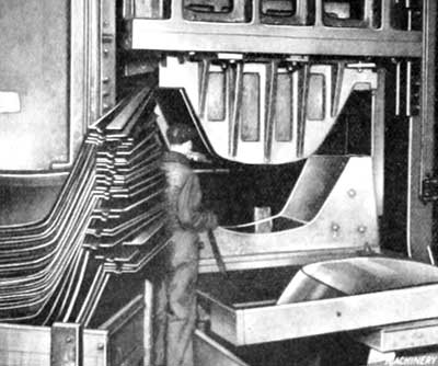
Large scale production of Child’s Meritas
bodies were
announced in the trades during 1924 and 1925:
Louisville, Kentucky’s Mengel Body Company
took out a Childs
license to build Meritas-covered sedan bodies for Ford Model T chassis
that
were offered through select Ford dealers. Pictures show a number of the
bodies
under construction in the Mengel plant.
The Henney Motor Co. of Freeport, Illinois
offered
Meritas-covered bodies as an option on its 1924-1925 lineup of
professional
cars, and surviving photographs reveal a number of the
‘baloney-skinned’
vehicles were constructed (the term being coined by Henney’s paint-shop
foreman, R. D. Ditzler, who was not a fan.)
Pacific Factory magazine announced that a
local firm, the Meritas Fabric
Body Corporation, was planning on constructing fabric bodies in
Los
Angeles:
“Auto Plant, Los Angeles, Calif.
“Meritas Fabric Body Corporation
will erect a
plant at Macy street and Mission Road for manufacture of coupe body for
light
cars.”
The April 1925 issue of The Automotive
Manufacturer announced
that the Fabric Body Corp. had purchased the Selden Truck Co., and was
planning
to construct fabric-covered buses at its Rochester, New York plant:
“Fabric Body Buys Selden Company for
$450,000
“Large-scale production of fabric bus bodies
will be carried
on at the Selden Truck plant in Rochester by the Fabric
Body Corporation, of Detroit, which on March 16 purchased the
Selden Truck
Company for $450,000.”
The Fabric Body Co. sold production licenses
to the Haynes-Ionia,
Merrimac, Sedan Body and E. J. Thompson companies who produced a number
of
one-off custom bodies for display at the 1923-1925 automobile shows and
salons
on Auburn, Apperson, Chrysler, Dodge Bros., Hudson, Lincoln, Marmon and
Moon
chassis.In Toronto, Ontario, Canada,
Brooks
Steam Motors Ltd. produced a few fabric-covered highway buses and cars,
announcing
that for 1925 “The new Meritas Fabric Body is standard
in Brooks cars.”
Ultimately the fabric-covered composite body
failed due to
the amount of hand-labor involved. Hayes-Ionia’s Roy F. Anderson
stating:
"While fabric construction does eliminate
two difficult-to-control areas in body production, metal working and
painting, experience in lots of five hundred suggests there can be
considerable
trouble with this construction as well as any other… Hand
labor has been the obstacle in the production of
fabric bodies,
perhaps due to orders which haven't been large enough to warrant
special
equipment and tools."
Few Meritas covered bodies were constructed
after 1925, and the
Fabric Body Corp. had withdrawn from business by 1928.
Apparently the Model Body Corp. had hoped to
manufacture
some of their own fabric bus bodies, the October 29, 1924 issue of The
Automobile (Automotive Industries) reporting:
“Thompson Made Head of Model Body
Corp., Company Is
Reorganized, New Capital Secured and Expansion Planned, amounting to
$110,000
“The Model Body Corp., 7201 East
Six-Mile Road, Detroit,
has been reorganized and additional capital put into the business for
expansion. The production of passenger car bodies will be
continued, but
in the future the company will also specialize in bus and commercial
bodies.
Walter F. Thompson has been elected president and general manager of
the
company to succeed G. L. Gast, who becomes vice-president. George
Mercer and C. Lester French continue as secretary and treasurer
respectively.”
Model Body Corp.’s listing in the 1925-26
Detroit Directories
follow:
“Model Body Corp. – 7201 Six Mile Rd. E.
Inc. ’19, Cap.
$110,000. Walter F. Thompson, Pres.; G.L. Gast, V-Pres.; George J.
Mercer, Sec. Treas.”
Walter F. Thompson (b.1874 in Conn.)
was formerly a
body engineer with J.C. Widman & Co., Detroit, his listing in
the 1921
Detroit Directory follows:
“Walter F. Thompson, supt. J.C. Widman &
Co. h. 2553
Lothrop av.”
G.I. McClure and H.M. Will were both
Detroit-based lumber
executives and the Model Body Corp. The factory was located in a small
industrial park located at 7201 Six Mile Rd.
Bus body production is doubted and its
listing in the 1926
SAE Directory no longer lists George J. Mercer as being involved with
the firm:
“Model Body Corp. (Auto bodies) Plant,
7201 E. Six-Mile
Road Detroit, Mich. Pres., W.F. Thompson; V.Pres., G.I. McClure;
Sec., H.
M. Will; Asst. Gen. Mgr., A. Kalinen; Pur. Agt. Norman Guinett.”
The Model Body Corp. last directory listing
was in the 1926
Detroit Directory and it’s assumed they withdrew from business sometime
during
1926. In 1927 their factory became the home of the Thos. V. Heston
Lumber
Co, a wholesale supplier of Hardwood — Cypress — B & B Yellow
Pine — Sugar Pine — Mahogany and White Pine Pattern
Lumber
Yard and Mill.
The facility at 7201 Six Mile (now E.
McNichols Rd.) remains
an industrial park, it entry being located to the right of the old
two-story
brick Michigan Tool Co. (now Pacific Motors) plant at 7171 E.
McNichols Rd. The buildings used by Model Body Corp. still exist and
are
currently occupied by the General Hardwood Company Lumber Yard and Mill.
George J. Mercer died in Detroit, Wayne
County Michigan on
November 23, 1952 at the age of 85; his death certificate states he was
born in
England in 1867 to George and Emily (Newman) Mercer.
© 2013 Mark
Theobald for Coachbuilt.com
The following few articles make up a miniscule
part of George J. Mercer’s monumental body of work:
Article #1 is from the March 13, 1913, issue of
The Automobile:
“Frameless Glass Windows for Automobiles
“By George J. Mercer Body Designer
“The use of frameless glass windows on closed
bodies is growing rapidly in favor. At the last Importers' Salon, held
in New York, at the Astor Hotel, Jan. 2nd to 11th, there were
twenty-two bodies having frameless glass while sixteen had windows with
wooden frames.
“There are, however, two very noticeable
drawbacks connected with the newer method. One of these is the
increased liability of breaking the glass, and the other is the letting
in of water when it rains or when the car is washed. The letting in of
water is not due to a mistake or fault, but is the accompaniment of one
of the methods used in operating the glass.
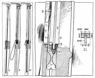
“Fig. 1, A, a cross section through the body of
a limousine, shows the door pillar with the glass suspended by the lift
strap. This window is of the frameless glass type and as illustrated
the glass travels in a straight groove extending from top to bottom of
the pillar, being supported at all times by the strap. The metal
channel in which the lower edge of the glass rests and to which the
strap is attached, is continuous across the whole width of the glass
between the pillars. This channel always remains below the top of the
bar and out of sight. The necessary clearance, however, to enable the
glass to pass by the back face of the bar without touching, is
sufficient to enable the water to enter. Where this method is employed,
provision is made at the bottom of the door and body for drainage, and
it the construction of the body is practically all metal no great
inconvenience is experienced.
“In some of the best bodies made this method is
used with apparently satisfactory results. The two strong features in
its favor are the safety with which the glass can be operated without
breaking, and the opportunity that it presents of utilizing a
mechanically operated lifting device. The disadvantage of this method
is that it permits the entrance of water in the glass pockets with a
consequent deteriorating effect on the wood framing of the body.
В and B1, Fig. 1, illustrate another method of
operating the frameless glass window. Two positions are shown and the
section of the body illustrated is the same as at A. These two
illustrations show a method employed to overcome the tendency of the
glass breaking when raised and lowered, and at the same time keep out
the water. В shows the glass raised and the entrance of water
effectively barred, while B1 shows the glass dropped to its lowest
position in the pocket.
“Fig. 2, an enlarged view of the door bar at B,
Fig. 1, better illustrates the glass in raised position. The wood
channel in which the glass moves up and down, is not one continuous
piece, but is parted and is put in the pillar in two pieces. The lower
half is stationary in the pillar and the top and terminates at A. The
upper half of the channel is fastened with one wood screw at the top,
in the center. With this screw as the pivot point the lower end of the
channel moves in the arc of the circle from С to D and
carries the glass with it. This channel terminates at the lower end at
BB. A cross section showing the dimensions of the channel is given at
El. At the rear of the glass the channel has a downward extension so as
to support the glass when the pull comes on the strap. Across the lower
edge of the glass is the metal channel K. The glass rests in this
channel, being first protected by a rubber channel that fits over the
glass and in turn fits into the metal groove. This metal channel К is
very strong, so as not to bend when the strap is drawn tight. At the
front the metal terminates in a lip or hook that slips over the fence
iron on the door bar, thereby forming a watertight contact that
prevents any leakage of water into the body. On the inner side the
channel is flat and to the center are fastened lugs that provide
attachment for the lifting strap. The position of the glass as
illustrated is with the opening closed, when the glass is supported by
the metal lip of the bottom channel hooking over the fence iron. In
order to facilitate an easy movement forward of the channel containing
the glass, a strong spring G, fitted with a roller at the end, is
pocketed in the side of the groove and presses constantly against the
channel.
“When it is desired to lower the glass, it is
first lifted slightly by the strap and then lowered, the two springs LL
guiding it into the groove of the lower channel that commences at A.
When in its lowered position the top of the glass is even with the top
of the fence iron and the springs LL perform the duty of holding the
glass rigid and prevent rattling.
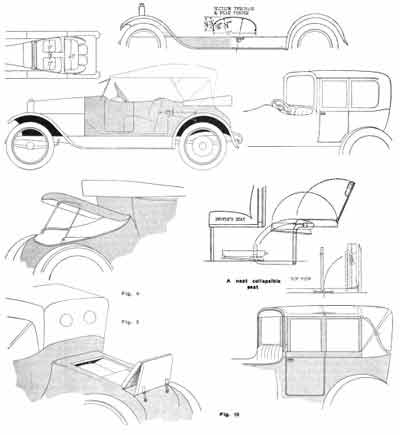
Fig.1—Sections showing two methods of fitting
Fig. 2—Watertight method of supporting window”
Article #2 is from the May 15, 1913 issue of The
Automobile:
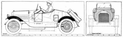
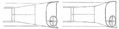
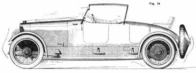
“Design for Streamline Runabout Body Body for
Edwards-Knight 25; Has Hood and Cowl in Continuous Line—Large Locker
Space Provided
“By George J. Mercer
“Sole Of Feet
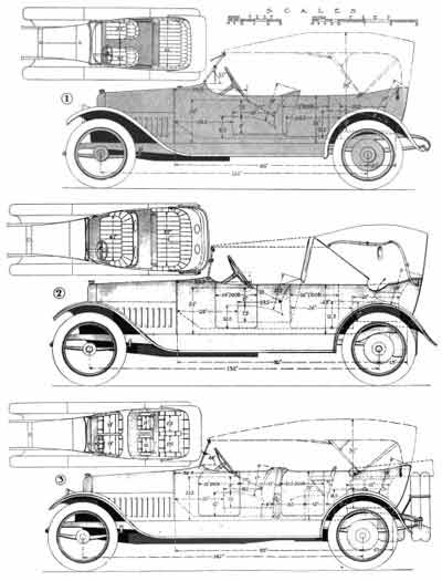
“A runabout body design possessing lines that
suggest power and speed is shown in the accompanying scale drawings.
The chassis to which the suggested design is applied is the
Edwards-Knight 25-horsepower model, which has a four-cylinder motor
with a bore and stroke of 4 by 5.5 inches, and worm drive. The
wheelbase is 120 Inches, and wire wheels, 36 by 4.5 inches with Q. D.
rims, are fitted. The frame is of the double-drop type which permits
the low body position in relation to the hood that is clearly brought
out in the side view, Fig. 2.
“It will be seen that the type of body shown
adapts well to the chassis, producing a robust and harmonious
appearance. The upward slope of the hood permits of the cowl being a
continued straight line and the minimum of wind resistance is thus
obtained. This effect is also enhanced by the slanted top of the
radiator.
“The application of wind-cutting surfaces is
the keynote of body designing today. Every inch of flat surface
eliminated from the front of the car means a considerable saving of
power besides having the additional merit of improving the appearance.
“The introduction of this feature in body
design will be noticed in Fig. 2, and the same idea is
carried out in connection with the sides, as shown in the plan. Fig. 3.
Flat or obstructing surfaces are avoided by blending the sides of the
body into the hood. The body lines are thus continuous in both sides
and top, producing a smooth streamline effect.
“The sizes of all doors are indicated in the
drawings. At the front of the entrance doors there are two good-sized
flutings on each side of the body for ventilating, in addition to which
there is a ventilating device at the base of the windshield This
ventilator is in the form of a half circle of metal with the ends
closed. The lower side is always open, while at the front, there is a
door, running the entire length of the opening, that is hinged at the
top and is operated by two wing nuts. This door can be opened to any
extent desired, and the semi-circular shield serves to deflect the wind
under the cowl and away from the faces of the occupants.
“This windshield is a new feature used in
conjunction with runabouts. The frame that holds the glass extends
along the bottom and part way up the sides, the top edge being glass
only and free from any obstruction to a clear vision. This windshield
as a unit can be swung to any angle, or lowered to lay flat on the cowl
The frame that holds the glass is of wood and is strengthened
considerably by the metal that forms the hinge. The ventilating device
is integral with the windshield and moves with it.
“A commodious locker compartment is provided at
the rear. This locker space, the large size of which can be
readily-noticed by comparison with the pair of suit cases shown in
dotted line in Fig. 2, is subdivided, and loading and unloading is by
means of three hinged doors, one on the top and one on each side These
doors are made watertight by having copings projecting from the body
.25 inch, over which the edges of the doors fit
Provision is also made for carrying two spare
wheels, the body being flattened off at a suitable angle to receive
them. The panel on the body at this point is depressed to receive the
projecting hub of the wheel. The fastenings are on the gasoline tank
and on the body.
For the construction of this body wide sheets
of metal are required. The cowl is one piece, forming the two sides and
the top and from the dash to the front of the door. The narrow sheet
under the door is separate, and is butted between the front and rear
sheets. The rear sheet extends from the rear of the door to the back
end of the chassis. It is cut off on line with the flat formed for
carrying the spare wheels and is then continued up to midway of the
top, where it joins the corresponding sheet from the opposite side.
This joint is a carefully made butt and the two ends are flush riveted
on the outside. On the under side is the customary reinforcing strip
that crosses the joint and through which the rivets pass. This joint is
not a very long one as the door or lid .occupies the greater part of
the distance from the seat line to the tire space. After riveting, the
joint is carefully wiped with aluminum solder.
“The size of the one sheet for the cowl is 74
inches by 18 inches, and for the two rear sheets 70 inches by 53 inches
each. All are of aluminum 16 gauge. Aluminum is the most suitable metal
for these sheets as considerable hand work is necessary and the extra
cost of aluminum over steel is infinitesimal as compared with the added
cost of working up steel for the purpose. On the flat sheet at the
rear, however, 22 gauge steel can be used to advantage. The joint of
this flat sheet with the side panels is covered with a molding.
“On the sides the small doors are cut out of
the flat stock, and, as mentioned before, the door openings, both of
the side and the top, are reinforced by copings that serve to shut off
the entrance of water. The framing inside is of wood, with the
necessary iron braces at the entrance doors and under the back end to
support the spare wheels. The divisions in the luggage compartment will
help in making the top rigid.
“This body presents comfortable accommodation
for two people, and in order to give a clearer impression of the body
proportions relative to the passenger, the figure of a driver 6 feet
tall is outlined in Fig. 2.
“With regard to painting, although this body is
odd in its outline, nothing of the loud in colors should be used. The
best combination is the dark blue so much in evidence as the body color
with black moldings and fine hair line striping of lighter blue,
together with black leather and black and nickel mountings.
“The appointments on a car with this type of
body are generally very simple, pockets on the doors being the only
part of the trimming of any importance. The horn is placed under the
hood and the electric side and headlights and the fenders are standard
equipment.
Fig.1-Front view, showing low position and
compact form of body design
Fig. 2 - Side elevation to scale of suggested runabout design adapted
to chassis of Edwards-Knight 25
Fig. 3 - Plan showing continuous streamlines of body exterior.
Fig. 4 -Rear view”
Article #3 is from the June 5, 1913 issue of The
Automobile:
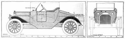
“Runabout Body Design for Paige-Detroit; Spare
Tires Carried in Concealed Storage Space at Rear -
Body Doors Oppositely Hinged for Ventilation of Interior
“By George J. Mercer
“There are three conspicuous essentials to
consider in body designing today. These are : First, the proportioning
of the body so that the comfort of the passengers is well provided for;
second, the elimination as far as possible of flat external surface
that would result in loss of power against the wind; and third, the
provision of adequate storage space for extra parts being carried on
the car.
“The first two of these essentials has received
careful consideration at the hands of the designers and the results are
used as talking points of considerable weight by automobile salesmen.
With regard to the third consideration, the provision of storage space,
however, this does not seem to have been given the attention that the
subject apparently deserves. Even when the space is ample the important
feature of accessibility is often ignored or insufficiently considered.
“One matter that is receiving more attention
than formerly is the disposal of the spare tires, though there is still
much to be desired in the way these articles are cared for. The storage
of tires inside the body has not met with the favor that it was
anticipated would be the case.
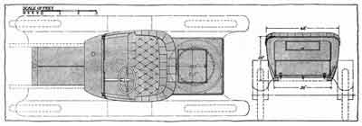
“A runabout body design with an interior
compartment for the tires is the subject of this article, and the body
is shown mounted on the medium-sized Paige-Detroit chassis, having
left-side drive, ii6-inch wheelbase, 34 by 4-inch tires, body space
back of the dash of approximately 91.5 inches and a rating of 36
horsepower.
“This car is especially adapted for rear
storage, as the gasoline tank is provided for at the front. This tank,
of approximately 14-gallon capacity, is standard equipment and is
indicated by dotted lines in Fig. 2. Taking the rear compartment first,
this is long enough to take nicely the two tires that are considered
necessary spare equipment for touring. Since the gasoline tank is
provided for in front under the hood, all the space at the rear is
available for carrying the tires and for luggage. In this case, the
tires being 34 inches in diameter it is an easy matter to provide
sufficient space. At the rear is a door large enough for the entrance
of the tires. This door is hinged at the top, and at the sides and
along the bottom and is made watertight by having a flanged lip, that
extends inward from the inside of the door. When closed this lip enters
a recess packed with either rubber or felt. At the top the hinge is
continuous and keeps out the water. Fasteners are placed at each of the
lower corners and in the center a hasp and padlock is fitted.
“The tires are set on a tray that slides on
rollers. To remove the tires, the door is first held open in the
upright position, and the tray rolled out as indicated by dotted lines
on Fig. a. At the back end a hinged leg, forming part of the
tray equipment, is dropped down for a support, while at the front the
tray rests on the slider. The inside space of the tires is utilized by
a drum that serves the double purpose of keeping the tires in position
on the tray and also acting as luggage space for small articles. At
each rear corner of the tray is a small triangular box that can be used
for small tools. This box thus utilizes the space at the corners not
occupied by the tires. Its shape and position is indicated on the plan
view, Fig. 3.
“Above the tire compartment the space is
utilized for carrying miscellaneous articles of luggage. This is
sufficient for one large or two small suit cases and have room besides.
The floor dividing the upper and lower compartments is one sheet of
metal and waterproof and there is suitable drainage, so that in case of
water leaking into the top compartment it will not be carried into the
lower compartment and do damage. An idea of the storage space that this
upper compartment provides can be obtained by reference to the side
elevation Fig. 2 in which a suit case 18 inches by 8 inches by 30
inches is indicated. The door on top is made watertight.
“The body interior has ample seating space for
two people. A generous thickness is allowed for in the trimming, and
there is a small locker space under the seat. The gasoline tank under
the cowl is not directly connected with the metal of the body; air
space is allowed all around. The filling plug is directly under the cap
on the cowl.
The electric dash lamps are placed flush with
the dash and the horn is placed under the hood.
“One of the novelties used on this design is
the Auster windshield. This shield is of canvas that is unrolled from a
spring roller and held in position by the two side arms as shown on
Fig. 2. On Fig. 3 the shield is shown folded and the arms are turned
down. When in use the angle of the shield can be made at will and as
the material is very light it can be folded away very easily. This type
of shield has most of the advantages of the glass shield without its
greater weight.
“The ventilation of the body is by means of the
doors entirely, that on the left side being hinged opposite to the
right door. By leaving both doors slightly open and as the openings are
in opposite direction a cross circulation of air is obtained.
“The standard equipment is utilized throughout,
including the front and rear fenders. The color specification for this
design cannot be improved over that of the stock car. Standard blue and
striping and black leather are as good and lasting in results as can be
desired. The quality of the material should be of the best for hair,
springs and leather if comfort is to be had after the car has seen
service.
Fig. 1 - Front view, showing position of
gasoline filler in top of dash cowl.
Fig. 2 - Side elevation to scale of suggested runabout design adapted
to chassis of Paige-Detroit 36
Fig. 3 - Plan view and rear elevation of suggested runabout body for
Paige-Detroit chassis.”
Article #4 is from the July 8, 1915 issue of The
Automobile:
“Trends in Touring Body Designs; Three Typical
Designs on Different Wheelbases Illustrated—Other Necessary Body Details
“By George J. Mercer
“The touring body still retains its place as
the most popular of body types for general purposes, it is used in
larger quantities than other models because it comes nearer meeting all
the requirements of an every-man's car and when made in quantities it
can be produced at a moderate price and yet have the smart appearance
of the to-order body.
The criticism of the open body is that it does
not afford the protection from dust that the all-weather or closed body
does, especially is this true of the occupants of the rear seat, who
are subjected to the dust raised by the air currents or eddies set in
motion by the irregular body side lines. The general adoption of the
flush-side, streamline, torpedo body has minimized this trouble and the
top serves as a shield both in its up and down positions.
“Developing the Body
“The name touring body is now applied in this
country to the torpedo model, the older form of touring model has
entirely disappeared, it survived for a time in a modified form by
having the fore doors added, but is now seldom seen. The progressive
steps in body development have been accompanied by very material
changes in the car itself: The engine hoods are now part of the body
line; the running boards and frame are lower; the dash lamps have
nearly disappeared; the radiator lines have been modified; the running
board shield has a blended surface from the board to the body line, the
guards have easy lines and the removal of the gasoline tank from under
the front seat, permits of the seat cushions being placed nearer the
floor, and left drive with center control affords a better line from
the body width to the hood.
“The body has been amplified also by better
windshield's, many of which are slanted back to overcome wind pressure;
the tops are mostly the one-man type, that do not require supporting
irons on the front seat. The attachment for holding down the top have
been improved as well as the place for attaching the side curtains.
During the past year, there has been placed on the market, a method of
inclosing the body for winter use with removable side windows that can
be attached to any car, making it nearly as comfortable as a closed
body.
“The public interest in style is in the present
and near-future modes and the three illustrations herewith, illustrate
the most modern of the conventional types, the illustrations show three
bodies of different size and design and on chassis of different length
of wheelbase. Two of the controlling features in a body design are the
capacity required in the body and the space provided on the chassis. Of
the various dimensions required to show the chassis space, the most
important is that from the back of the dash to the center of the rear
wheel. The wheelbase of a car is misleading when applied with reference
to body space, because two cars may have the same wheelbase, and if one
is a six-cylinder and the other a four, the engine hood of one will be
longer than the other and consequently the front wheel of one will be
further forward of the dash not less than 6 in. than the other, and the
body space of a six will be 6 in. or more inches shorter than a four
and yet have the same wheelbase. This is indicated on the designs.
“These illustrations serve both to show the
design and to carry the dimensions in figures of the most essential
sizes on all views, and all three designs have the up-to-date feature
of having the top line of the seat inconspicuous. The seat cushions are
closer to the floor than formerly, and to have the proper height for
the seat back and still maintain the low-looking body, the cushions are
tilted toward the rear so that the sitting position is partly a
reclining one.
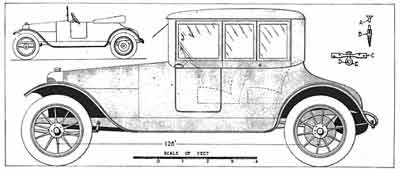
“Three Typical Designs
“The three designs are shown respectively on
chassis with 122-, 132- and 142-in. wheelbases and the seating capacity
is for four passengers on one, five on the second and six on the third.
“One design has central doors, one has
staggered doors and the large body has four doors.
Fig. 1 is the four-passenger body, 122-in.
wheelbase chassis, having 32-in. wheels and the gasoline tank placed
under the cowl. There are two doors that are placed centrally, one on
each side, and the passage to the front seats is by the aisle between
them. The front seat is built in from the body side top line and this
line is unbroken from the cowl to the rear, terminating in the
graduated upward back seat line.
“The top edge of the body is rounded over from
the outside with about 1-in. radius and the metal panel is fastened to
the inner edge of the wood framing, the joining being covered by the
trimming, which latter does not appear noticeably above the body line.
“The making of the body shell has become
increasingly difficult for the custom builder as the styles have
advanced and the accomplished, successful acetylene welding of aluminum
panels has come at a time when it is very much needed, where the
quantity of bodies to be produced are of sufficient number to warrant
the expense of forming the shape in molds or dies, so that steel can be
used for the panels, the process of manufacture is simplified.
“Features in Design
“On the design here illustrated, the front of
the body, from the door line forward, including the two sides and the
cowl will be made in three pieces, for sake of economy in material and
handling. The joints where the panels meet can be successfully welded
so that the surface will be perfect for painting and have the strength
of a single sheet of metal. The rear panel can be either in one or two
pieces and the doors are made without moldings to cover the joints. The
entire absence of moldings is one of the characteristics of modern body
designing, the influence exerted by the desire to have the unbroken
surface for stream line effect has been the principle reason, and, also
builders for years have endeavored to have the same outward appearance
to a metal body, that a wood panel body presents.
“Aluminum or steel may be used for panels
according to the facilities of the builder for shaping the metals.
“The sides of this body are low, 22 in. only,
and the cowl is 1% in. higher than the rear of the body. The cushions
are low and the room in front of the seats is long to compensate. The
doors are 21 in. wide and open toward the rear. The steering wheel is
well back from the dash and low and the distance from the dash to the
center of the rear wheel is 88 in. The body space is 12% in. more or
100% in. There is a foot rest for the rear seat as shown on the plan
and all the essential dimensions including the tilt of the windshield
are indicated. The shield is in two pieces, the lower part shown
inclined inwardly to ventilate.
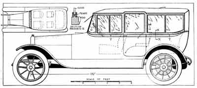
“Five-Passenger Design
“Fig. 2, shows a five-passenger body mounted on
a 132-in. chassis, with 34-in. wheels and the gasoline tank at the
rear. The distance from the dash to center of rear wheels is 92 in. and
the body space 13 in. more or 105 in. The required dimensions are
registered on the two views and are self explanatory.
“This design differs from the previous one in
that the rear seat is wide enough for three persons and the hinged
armrest, folds into the trimming at the back of the seat when not in
use and when down, and forms a partition, dividing the seat into two
places. Another difference is the style of top, which is a Victoria.
The windshield at the rear of the front seat, is high enough to meet
the top edge of the front bow of the top and so prevent the wind
entering. It carries two celluloid lights and for stormy weather there
is an extension, indicated by dotted lines, that is fastened with
buttons to the front of the top and to the top of the front windshield.
When not needed it is folded away.
“The Victoria top adds a pleasing look and when
used in conjunction with the shield, as illustrated, the drag effect
due to wind pressure is minimized. To obtain satisfactory working
results in raising and lowering the top, the covering should be some
other material than leather. Leather looks by far the richest, but
better knockabout results are obtained with a more flexible goods. Kaki
looks well, it does not show the dust and will not crease. The shield
can be covered with the same material, and the extension roof and the
slip covers can be the same.
“The shield is made to be stationary, and is
oval shape steel rod. The frame and method of covering are identical
with the practice used on carriage dashes. The two studs at the bottom
engage the socket irons that project from the back of the seat, and
nuts on the under side keep same in place. The celluloid lights are
stitched in the same as on the top curtains.
“The sides of the body are a trifle higher than
Fig. 1, and the increased body width, makes the seating proportions
very generous when used for four passengers, but there is ample room
for the five when required. The description of the construction is
generally applicable for both bodies. The doors are without moldings
and the top edge of body side is rounded, the front door opens toward
the front and the rear door toward the rear, all hinges and handles
being concealed.
“A Six-Passenger Body
“Fig. 3, is a six-passenger body mounted on a
142-in. wheel-base chassis having 36-in. wheels, gasoline tank at the
rear, and the distance from dash to center of rear wheel being 95 in.
The body space is 15 in. more or a total of 110 in.
“This design has in common with Figs. 1 and 2,
doors without moldings and the top edge of body rounded as well as the
graduated top line. This line blends into the cowl forming the top of
the front seat back. The body sides are higher than Figs. 1 and 2, and
under the cowl at the rear, the extra seats are folded when not in use.
They are shown in dotted lines in this position, as well as in the
position for use. Above the space required for stowing the seats, there
is room for small lockers, opening outward in the tonneau.
The dimensions amply located on the two views,
show without further description the capacity and size of the body. The
doors are four in number and the front line is curved to avoid the bent
line of the cowl as it meets the side line of the body. They are made
without moldings and open in opposite directions, this is optional, as
all doors can open toward the rear if desired.
“Upholstery Features
“The plan views show two trimming designs.
Figs. 1 and 2 have a long pipe caught with buttons and Fig. 3 is a
design with the Turkish or arm chair upholstery. This latter is the
newest style and makes a pleasing looking car and is made thick so that
it is very comfortable. The leather for this trimming design must be
very pliable and the straps serve the same purpose as the buttons on
Figs. 1 and 2. Design 3 has also the advantage of being easily kept
clean. Leather is still the most preferable material used for open body
trimming, some motor cloth is used and on cheap cars the imitation
leather is finding favor and is being used more than formerly.
“The principle change made in trimming these
styles of bodies, has been the doing away with the roll of trimming
that appeared above the side line of the body and seat, in some cases
it appears slightly above, but on the majority of new cars it has been
lowered out of sight.
“The appointments include the regulation cigar
lighter and ash tray and clock, and there are pockets of the doors and
robe rail and foot rests, the robe rails are mostly the flexible kind
made of a strap and fastened to the rear of the front seat, and the
Auster windshield at the rear of the front seat is used more than
formerly.
“Door handles on this type of body are all
inside, and the hinges are both the concealed and the outside curved
hinge, linoleum is the best material for floor covering for the toe and
foot boards and running boards and leather bound carpet in the tonneau.
The top material is either Burbank or Pantasote and the Victoria top
goods should be kaki or bur- bank, preferably kaki. The extra tires are
carried at the rear on most cars and the preponderance of color designs
are dark shades and blue predominating.
“These illustrations are intended to serve the
purpose of presenting the design of each model, amplified by dimensions
in figures and the description above given is intended to supplement
the above two thoughts up to this point only.
Fig 1.—Four-passenger body on a 122-in.
wheelbase chassis with 32-in. wheels. Two centrally placed doors are
used with the front seat built in from the body side top line.
Fig.2—A five-passenger body on a 132-in. wheelbase chassis with 34-in.
wheels. In this design the rear seat is wide enough for three persons
and the hinged armrest folds into the trimming when not in use.
Fig.3—Six-passenger body mounted on a chassis of 142-in. wheelbase with
36-in. wheel. This is a four door body and the front line is curved to
avoid the bent line of the cowl as it meets the side line of the body.”
Article #5 is from the November 25, 1915, issue
of The Automobile:
“Two Demountable Top Designs Entirely New Type
of Body May Evolve from Present Closed Car Development—Types for
Apperson Runabout and Chalmers Touring Car Chassis
“By George J. Mercer
“The demountable top fitted to touring and
runabout bodies is becoming increasingly popular each year, and the
coming winter bids fair to outrival in numbers the total output of the
past seasons.
“The quality of the work and the designing both
show improvement, which is no doubt due to the large number of good
builders giving their attention to these matters. The demountable top
has arrived at the stage where it is accepted as a staple article of
manufacture that the public must have. Unquestionably the largest
number used will be the type that can be sold complete and assembled on
the body, for $75 to $160 as it is for cheapness that the top has come
into existence and the majority of buyers are those who expect to
economize.
“A great range of possibilities is open to the
body builder when converting the open body into a closed one. Some use
the regular four-bow or the one-man top that is already on the car and
simply add side glasses with a framework to hold them in place. In a
few designs this addition is made in such a way that the top can be
folded down by simply taking out the glass frames. In the majority,
however, the entire framework has to be removed in order to fold the
top, and this is done only at the beginning and end of the season.
There is a considerable increase in the number of car manufacturers who
provide a demountable top as regular equipment, and the number will
increase in the near future. Eventually a new body design will evolve
out of the present efforts.
“Novel Body May Evolve
“A very good business is being done by
individual builders who specialize in converting the bodies in use into
closed cars, and this affords a field for all the ingenuity that is
latent in the body mechanic. The average body design is stereotyped
before the public becomes familiar with it, and the body builder simply
makes a copy, taking another body as a model. But supplying the
demountable top is a free-for- all race, and it will be strange if in
the near future a distinctively novel body is not brought out, that
will be as distinctive as was the flush-side body type.
“The standard forms of collapsible bodies of
the better class, such as the landaulet and the cabriolet, have the
distinctive look desired by the buyer who can afford the price, but the
full leather top lacks the adaptability that the knockabout car owner
needs. A fine carriage body is like a pair of shoes to many people; it
only becomes comfortable about the time it is nearly worn out. The
rough and ready demountable body, that does not involve the expenditure
of much additional money, has the right seasoning to make it popular
with a large number of car owners.
“All Bodies Easily Converted
“There are many manufacturers who are prepared
to furnish tops for the standard makes of cars at short notice. They
are equipped with forms that correspond with the bodies, and they only
require the car, first long enough to check up the measurements, and
then later on to assemble the top. All the modern bodies are easily
converted, because the trimming roll at the top of the seats does not
extend appreciably beyond the body line and the top line of the body is
of such a shape that the assembling of the upper framework is not
difficult. The worst feature is the adjustment of the hinges, that is,
provided hinges are used on the upper part, as most touring doors are
made to drop downward when open,
and do not swing horizontally. A great deal of
ingenuity has been used to overcome this, some builders making a
complete new door that replaces the old one, others placing one long
hinge at the top, which projects sufficiently to enable the upper part
to swing true with the lower section, but the majority, especially the
lower priced designs, do not attempt to have the hinges line; each
section has a movement of its own and there is a finger projecting down
on the inside of the upper section which engages in a slotted plate on
the lower one, this finger traveling in the elongated slide and keeping
the two parts in unison when opening and closing, the finger and slot
compensating for the different lines of travel. A similar arrangement
is made for the lock, the handles in the upper part operating the lock
below.
“An Apperson Runabout
“Fig. 1 shows the Apperson four-passenger
runabout with demountable top added and Fig. 2 shows the body without
it. To make this top as illustrated, the bow top and the windshield are
first taken off and the lower ash rail forming the support for the side
glasses is fitted to the shape of the body top line; the rail is cut,
part being attached to the door and part to the body and the cut must
be made a little back of the door line in order that the part on the
door will clear when opening. The jutting out of the added piece beyond
the door panel enforces this cut being offset. The side rail continues
around the back, the back part not being so deep, and uprights are
framed behind the side glass and at each side of the back light; the
latter is a separate frame and is screwed to the posts and toprail. The
toprail is framed to the posts and the front pillars and the roof is
formed with bows, sawed to form the shape of the roof corners, the
front pillars are connected at the bottom by a bar that fits close to
the cowl panel and the whole front is fastened by irons that engage in
the sockets formerly used for supporting the windshield.
“Framework Is Light
“All the framework is light except the front
pillars, and these must be wide to fill the space from the door to the
windshield supports. The side glass frames are wood, 11/16 in. thick,
and they are held in place at the bottom by resting over a bead, in the
manner illustrated in Fig. 7, section X-X, the wood frame
being grooved to do the same duty as the metal frame in the
illustration. This bead keeps the rain from entering and at the top the
glass frame rests in a rabbet in the toprail, the rabbet being open
toward the inside. There are two limousine window fasteners for each
frame, to remove or place the glass frames in position and the
fasteners are screwed back until the frame tilts sufficiently to allow
it to be lifted over the bead at the bottom. On the rear, the vertical
edge of the door glass frame and the one directly back of the door, tee
molding is fastened to cover the openings between the frames and at the
rear of the third side frame; a rabbet in the post covers the opening,
while at the front the pillar has a regular door rabbet. There is no
framing between the front and rear side pillars and, when desired, all
the side can be open, the four frames can be stored under the seat and
the door glass frame is made to be turned down inside the door. The
hinges for turning this frame down are placed inside with the centers
on line with the bottom of the frame. When up, it is held stationary by
two set screws that, passing through plates on the inside of the door
top frame, engage in lugs projecting from the under edge of the frame
that enter slotted plates on the top face of the framework.
“Original Hinges Used
“This glass frame forms the upper part of the
door, it strikes against rubber bumpers on the toprail rabbet when
closed and there are no other turning hinges used than originally are
on the job. It projects back of the door line at the rear enough to
line up with the line of cut in the framing, and at the front of it is
back of the door line enough to give door bevel, so that it will clear
when the door is opened and the frame is down. Also the hinge on the
frame is long enough so that space is left between the frame and door
to permit free operation of the link connecting the door handle in the
framework to the handle of the lock.
“The front windshield is in two parts; the
upper is a visor and the lower swings inward for ventilation; the back
light is square cornered and 13 in. high by 24 in. long is the maximum
size, though it can be as much smaller as desired, the glass in this
being stationary.
“The roof can be all metal covered, or metal
can be used to form the rounded corners and canvas or top cloth of any
waterproof variety stretched over this and fastened under the moldings.
The back panel will be metal also, while the lower side framing and
front pillars will be painted wood.
“Attaching the framework to the body in a
manner that will leave few or no blemishes when the top is removed
requires careful planning. Advantage is taken of the regular body top
irons on the job to do most of the work of fastening as there are
always four and sometimes more. In this case, the forward ones are
quite long, and a cap is shown covering this. Diagrams C, D and E, Fig.
3, show how the supports are used; D is the gooseneck on the body, E is
an eye bolt that slips over D and the end engages in a hole in plate С
which is fastened to the upper framework. When assembling, the top is
down until the four bolts E enter the plates С and the nut is tightened
until С rests on the shoulder of the bolt. These bolts take care of the
rear, of the top, and the trimming is left loose at these points so
that the nuts can be turned up from the inside.
“Forward of these supports, and on the doors, A
and B, Fig. 4, are used. Вis a lag screw with the head cut off, drilled
and tapped to receive a 12-24 machine screw, and a sufficient number of
the screws В are set in the top framing of the body and door, the top
of the bolt coming flush with the finish molding.
“The upper framing is carefully fitted to the
body line, the holes in the bolts B located and the framing is bored
and countersunk for the screws A. When the framing is very deep A and B
will not suffice and, in addition, angle irons are used with one leg
screwed to the under side of the framing and the other extending down
inside the body. Screws are put through the trimming into the body
frame and finish screws are put in all screw holes when the top is
removed, this being also done with the screws B.
“On a Chalmers Touring Car Chassis
“Fig. 5 is a large seven-passenger touring body
mounted on a Chalmers 132-in. wheelbase chassis and the top is modeled
from the lines of the Brewster sedan. The door for this job is the same
as for a closed body; it is in one with the top and the glass is made
to drop into pillar slides and entirely disappear. The forward
triangular glass is flat and stationary, pointing in toward the front,
in order to follow the side sweep of the body as indicated on the
miniature plan view, Fig. 6. This view also clearly indicates the shape
of the windshield glass.
“The other four glasses on each side are held
in place at the bottom as indicated by the diagram X-X, Fig. 7. The
glasses are metal bound at the top and slide in a groove in the wood
toprail, while limousine fasteners keep them tight. They are placed in
position by sliding in from the doorway, the posts at the front and
rear of the door being made with an outer and inner member, the space
between allowing the glass frame to enter. When not required, these
four side glasses are taken out and stored under the seat, or one can
be taken out to give extra ventilation and the companion glass can be
pushed forward or back to control the air currents. As before
mentioned, the door glass drops and is guided by a lift strap. This
glass is frameless. The front windshield has the vision, the lower part
is stationary, the ventilator in the cowl compensates for a moving
lower windshield and there is also a ventilator in the roof. The back
light is stationary.
“Framing Up the Top
“The method of framing up this top is identical
with that described for Fig. 1. The line of separation of top and body
is on line Y-Y, Fig. 5, a tee molding covers the joint, and the side
glass frames are provided with a lip that meshes with its companion
glass frame. This keeps out the wind and rain where the two frames join
in the middle to form the sides at the back and front of the door. The
same method of fastening is also used for top and body as shown in Fig.
1, and the door, being made for the purpose, has the lock handle in
line to operate the lock without connecting links. The back panel is
sheet aluminum in one piece from side window to side window; the roof
can be of the same, or the round of the roof can be formed of metal as
far up on the roof as where the radius of the corner starts, and then
canvas or waterproof top material can be either drawn over the whole
roof from side to side and fastened under the drip moldings, or the
metal corners can be finished to paint and the roof cloth can form the
center deck of the roof, being fastened under moldings running from
back to front along the inner edges of the metal forming the corners.
“The popular color for painting for the
Brewster sedan is the color generally called battleship gray, and the
finish is dull, while the part that here is designated as the
demountable roof, would all be finished dull painted inside with no
trimming of any description showing above the waist line, or the line
that corresponds with the top of the seat back trimming, when painted
inside. All the woodwork, such as the bows, etc., is nicely rounded and
the framing shows very light in size. For Fig. 1, a suggestion for
trimming that is commonly used is to cover the seats and backs, which
are of leather, with slip linings and line the top with a similar
material, this making a uniform appearance inside the body which is not
too expensive.
“These two designs are drawn to scale and there
is sufficient information conveyed to enable the top maker to duplicate
them full size. The cost of making a top from either of these
illustrations will vary from $250 to $400.
Fig. 1 - Center - Apperson four passenger
runabout with suggested design of top added.
Fig. 2 – Upper Left -The same body with ordinary type of top.
Fig. 3 - C, D and E showing how the supports are used in attaching the
framework to the body.
Fig. 4 -A and В -showing how the screws used are made to Insure their
tops coming flush with the finished molding In securing the framework
to the body.
Fig. 5 - A demountable top for a seven-passenger Chalmers touring car.
Fig. 6 - Miniature plan view of this construction, showing how the
forward triangular glass Is flat and stationary to follow the side
sweep of the body toward the front.
Fig. 7 -X-X -showing how the four glasses on each side of the top are
held In place at the bottom. The glasses are metal bound at the top and
slide in a groove In the wood top rail, limousine fasteners keeping
them tight.
Fig. 8 Y-Y -showing the line of separation of top and body. A tee
molding covers the joint and the glass side frames are provided with a
lip that meshes with its companion glass frame, keeping out the wind
and rain.”
Article #6 is from the January 20, 1916 issue of
The Automobile:
“1916 Body Design Is Uniform; Best of Last Year
Is Now Average.
Form, Color and Comfort All Improved at Both Palace and Astor Shows
“By G. J. Mercer
“In the Palace and Astor Hotel shows just
concluded, present in the body designs displayed, a more uniformly
worked out plan to develop the streamline effect, than in previous
years. This is particularly noticeable in the fore part of the car, and
in both shows, with the exception of a negligible number, the line from
the radiator to the body both on the sides and the top, presents a
graduated surface, so that viewed from a distance, in many cases it is
difficult to determine just where the engine hood ends and the body
proper commences.
“The Palace exhibition outshone all previous
years in color combinations, there were very good combinations shown on
a runabout in yellow and black, also a canary and black coupe, a red
runabout with pearl grey wire wheels and black moldings; a touring body
had cream and brown with Spanish leather. There was a dark grey sedan
and a very pleasing grey and black sedan; a dark grey limousine, a
coffee and black touring body, a wine colored coupe, a green and black
touring body, a wisteria sedan, a white and grey limousine and a white
and black limousine. These are a few of the best combinations, most
were in good taste, only a few violated the rules and had combinations
that made a glare in place of a pleasant sensation.
“In the Astor show the color combinations were
less conspicuous than at the Palace, grey or white and black, and
yellow and black were used, but not extensively, and the trimmings were
suitable to match the car colors; in one Armstrong closed body, and in
one Holbrook open body, a soft undressed leather trimming was used; the
majority had the regulation cloth goods with dark leather for the front
seats.
“In the following not all the good things at
the shows have been enumerated, nor have all the commendable designs
been illustrated, but to the best of the writer's ability, those things
that are of interest to the greatest number have been given prominence.
Both shows serve their separate purpose and as long as one is not a
duplicate of the other there will be room for both, one the
manufacturers' exhibit of standard make, and the other special designs
particularly in bodies, for those that are desirous to have automobiles
custom made.
“Smoother Bodies at Palace
“Returning to the consideration of body shapes
as noticed at the Palace show the first point is that the sides of the
bodies have a smoother surface, due to the absence of moldings. This is
true even of the doors, where the customary tee molding has been
replaced by allowing the panel sheet to extend and cover the door
openings. The top line of most of the touring bodies and runabouts and
the driving compartment of closed bodies show rounded edges and on
these closed bodies the overlap panel in which moldings are not used to
join the upper and lower panels, was the rule and not the exception,
also the seat trimming roll does not show above the body line, or if it
does, it is very much reduced in size over former years.
“There are fewer slanting windshields than was
to be expected, considering the general desire to eliminate wind
resisting surfaces, but there are more shields placed on top of the
cowl panel and forward of the rear edge of the cowl and there are fewer
cowls having the extreme upward tilt to the top line, near the shield
seating.
“Touring Body Holds Position
“The touring body still holds its own as the
most representative member of the automobile family, and the type with
a second cowl, not only shows a large increase in numbers, but the
effect of its popularity is proved by the desire to imitate it, by
minimizing the height of the driving seat back, and in some cases,
rounding it to give the appearance of half a cowl. This tends to give
the bodies a lower appearance and the elimination of the trimming rolls
helps to accomplish this end. In reality the bodies are lower, measured
at the seat back, but the sides are slightly higher; 24 to 25 in. is
the average side panel height. The aisle between the driving seat also
shows gain in numbers and in some cases the second cowl itself is
divided.
“The disappearing seat, despite the fact it is
not so roomy as the older form of side seat, has proved to be the only
style that is acceptable on both open and closed bodies, and the most
popular is the one that folds into the back of the driving seat.
“The four-passenger clover leaf runabout is the
new idea this year. Last year there was one three-passenger body, and
while, now, the majority on exhibition were only comfortable seating
for three, there were two, the rear seat of which could accommodate two
adults and one of these bodies was 42 in. wide on the cushion by 24½
in. from trimming or rear seat to panel of front seat.
“One expected to gee quite a number of good
looking designs of demountable tops fitted to touring and runabout
bodies, the demountable top has been featured so much in automobile
advertising of late, that naturally we looked for a better showing than
there is. The Kissel, which is one of a very select few that look like
jobs, showed one car with the inside stripped of its trimming, showing
the method of attaching and detaching the upper section so it could be
readily understood. The other tops exhibited have the effect of marring
the general clean look of the body by the excessive width of the
framing pillars, which only proves that to make a successful
demountable top, it must be made with the body as part of the original
design and not added as an afterthought.
“The permanent-roof body shows increased
numbers over last year. The regular Springfield body is on a number of
cars and there is an adaptation of the Springfield idea on two others.
Pierce had a body of this type in which the pillars fold down inside
and are fitted with an automatic hinged arm for holding them in their
respective positions. The only full collapsible all-weather body was
exhibited by the Springfield Metal Body Co.
“Few Innovations
“The Palace show from a body point of view, had
practically no features that were innovations, the average this year
was virtually the duplicate of the best in the show last year and many
of those that excelled last year, had the same exhibit this time. The
Palace average was very good in finish, design and workmanship and
novelties were conspicuous by their absence. There were fewer closed
bodies in proportion to the total exhibit than formerly, but town cars,
which have never been very numerous at this exhibit, were about the
same in number and are of better design than formerly, but there is one
feature in which this show outdid all its former records, and that is
in colors. Hardly an exhibit but had its white or white and black, or
yellow and black, or grey, or some other light color, and the striping
of the hood and wheels was louder and more prominent than ever.
“The word streamline has become the synonym for
the latest in body design and is used indiscriminately for every body
that shows a tapered line from the radiator to the cowl. Truthfully
speaking the only bodies that approach the true streamline effect are
the runabouts. To understand this, imagine a shape exactly like an egg
placed on wheels, the large end toward the front, as the egg moves
forward separating the air, the pressure of the atmosphere is increased
by the displacement, and as the air currents pass along the sides, due
to the egg moving forward, they meet easily and without clashing at the
tapered rear end, and no revolving eddies or air currents are set up to
disturb the road dust as the body passes forward. No body design in the
near future is going to be built along these ideal lines, except the
before- mentioned runabouts, no real necessity exists to disproportion
the rear end of a limousine or a touring body to make it egg-shaped and
there is also the item of additional cost of construction. The fore
part of the body that breasts the wind, is the part that has a
commercial value, and eliminating the flat surfaces at the front and on
the sides is the real money saver. Summing up the above logic, the
writer suggests that "fore-streamline" would be a more applicable term
to use, as it would cover all that we are trying to accomplish in body
designing at the present time, that is, giving the front of the car the
minimum of resistance.
“A new style body by Bender and Robinson on a
Singer chassis at the Astor show
“Figs. 1 and 2 show the plan view of the hood
and cowl of two touring bodies at the Palace, Fig. 1 is the newest
design and there is a taper of approximately 6 in., each side in the
length of the hood. The body line continues from this without a ripple,
to the widest part, this being a fine example of a fore-streamline. Of
stock cars the Mercer is one of the best of this class. Fig. 2 is an
example of one of the more conservative makes of cars, it marks a
slower growth and lacks the bold straight appearance that characterizes
Fig. 1. The top line of the hood has the same appearance on most cars
as the side line of Fig. 1, from radiator to dash, the average raise is
2 to 3 in., the radiators are similar to last year, those with the
slightly rounded edges predominating.
“Figs. 3 to 8 are sketches of Palace show
bodies.
“Fig. 3 is an example of the lowered driving
seat back rounded over like half a cowl, on this particular body the
back below the cowl had two compartments that are used to stow away the
top curtains.
“Fig. 4 shows a runabout deck cover supported
in the open position by arms that travel in slides at the bottom and
drop into pockets at the slide end when raised.
“Fig. 5 shows the rear seat of a runabout and
the method of locking the lid in position to form the back, it shows a
cheap way to make a seat in a small rear compartment and still be able
to raise the lid when the top of the car is down.
“Kissel All Year Is Sound Job
“Fig. 6 is a diagram of the interior of the
Kissel demountable top body, A shows the lock that fastens the upper
part of the door to keep it from rattling, it engages in a plate in the
body pillar and is operated by B, this lock is operated by the inside
or outside handle and the push rod moves up and raises A and when the
handle is released A drops into its place in the pillar, the push rod
rests in the lock A and disengages itself when the top section of the
body is lifted off; C shows the attaching lugs; the bolts used to
fasten these are always accessible, being covered by flaps in the
trimming.
“Fig. 7 is a four-passenger runabout adapted
from the clover-leaf idea the plan view shows the seating arrangement
and the second cowl is divided by a passage way.
“Fig. 8 is the outline of a town car body on
the Owen Magnetic, there is only one door for the driver on the right
side, the glass space at the front is unusually large and has rounded
top corners, the driving compartment is joined to the body by a second
cowl; this body was one of the best designs exhibited.
“Low Appearance Favored
“The coefficient of streamline in body
nomenclature is low looking and the effort to produce this effect has
replaced 36-in. tires with 34 and 32 sizes, the running board has come
nearer the ground and a little additional kick up to the chassis frame
sends it down forward of the rear wheel. The double drop to the frame
has not had many converts. Pierce did this in place of reducing the
tire size. The optical effect of raising the hood and cowl helps to
make the touring and runabout look lower, but the greatest gain has
been in lowering the seats, since the gasoline tank has been placed at
the rear. The driving seat has been lowered 3 in. on touring and about
6 in. on runabouts and the slant of the cushions is about 2% in., so
that on touring bodies the driver actually is about 5% in. lower when
seated than formerly. The seats have been moved farther back to allow
the extra leg room required when seated low and the steering wheel has
been lowered and the column lengthened to accommodate the seat, in many
bodies the driving seat is now made adjustable, because the driver
sitting more straight out than formerly, it is not practical to expect
men of different heights to accommodate themselves in the same sitting
space. At present this is only done on touring and sedan bodies where
the aisle between the seats makes the driving seat a free agent. On
closed bodies, such as limousines, etc., the driving seat is much the
same as formerly, on account of the necessity of having the door to the
body as large as possible, and the driver is placed as far forward as
freedom of movement and the proper room to sit will permit.
“Cushion Height Decreasing
“The average height of the front and back seat
cushions from the floor at the front of the cushion is 15 in. on
touring bodies with an average slant of 2% to 3 in. This applies to the
rear seat in closed bodies also. There are a few touring bodies in
which the rear seat cushion is only 12 in. up, but this is a height
that no woman can either sit down on or get up from comfortably. The
average height inside from floor to under roof in closed bodies is 55
in. One body at the Salon had only 50 in. height and there are several
that are only 53 in. Years ago 58 in. was considered the proper height
and from present indications 54 in. will be the average height for all
stock bodies. The average height of the seat back on touring bodies is
15 in. for the front and 18 in. for the rear.
“The instrument boards on nearly all the cars
seen at the Palace are similar designs to last year, and though
arranging the indicators in this manner gives the car a machine-like
look, there is a disadvantage and expense when the bodies are changed,
and there was more than one comment that this is a thing that is being
overdone and should be made less prominent. One body at the Astor Hotel
had the clock and speedometer at the rear of the driving seat and the
balance of the indicators on the dash just above the toe boards, this
left the cowl free and clean-looking and one felt that it would be easy
to enter this body and not bump the shins, although the seat was very
low. It is safe to predict that a year hence will see a change in the
location and appearance of this feature.
“One Person Tops Universal
“At the Palace one-person tops were used
exclusively, a few touring bodies had victoria top, there were more
wire wheels used than last year and the dash lamp was only noticed on
two makes of cars, the extra shoes or tires were carried in nearly
every case at the rear and there were more guards of the crown type
than ever. Fig. 9 shows the Chalmers front and rear guards and the
cross-section shows the shape of the top line. The trimming material of
the touring and runabout bodies is mostly leather, a few have the
imitation and a few Spanish leather with fancy colors. Only one body in
the show had the Turkish style of trimming, all the rest had either the
straight pipe with few buttons or the older form of pipe and point.
“The electrics from a casual glance appeared
like the display of last year, except that there was less conspicuous
trimming used inside and more color used in the outside painting.
“The closed bodies were modest in design, no
job had the full rounded or extreme dip to the roof line, there was a
tendency to flatter roof shapes, two bodies had chauffeur lights,
nearly all had the double vision windshield and regulators were used on
the windows almost exclusively. Several had fancy trimming combinations
and some had the broad black and white striped trimming, this was
nearly always accompanied by white and black painting on the body and
chassis. The coupelet designs were identical with last year and the
coupes were all large and had the extension window forward of the door,
and room for four inside.
“At the Salon there was enough new in body
construction to satisfy the exacting and the curious as well as those
who are really interested in watching progress. The new bodies were
practically all closed ones this year as against previous years when
open bodies represented the bulk of the innovations.
“The exhibits of Brewster, Healey, Locke,
Bender & Robinson and the foreign bodies of Barker & Co., as
well as the bodies of the Fleetwood Metal Body Co. and Hayes &
Miller Co. all came in for their share of notice. Fig. 10 is a semi-
touring body, Healey and Holbrook showing some of this type. The top is
fully collapsible and the ease with which one man can operate it was
demonstrated at stated intervals on the Healey body at the Locomobile
exhibit. At the rear pillar are landau springs to assist in carrying
the weight while lowering and raising. The front pillars fold down, and
the manner in which the top part collapses is indicated in the diagram
plan view; the top is of leather and is lined inside in light grey
cloth. The body makes an attractive design, having the advantage of
being easily converted into a closed, and open car, or the sides can be
entirely opened after the manner of the well understood permanent roof
bodies. Fig. 11 is also a Healey production, and has one of the two new
folding seats at the shows; the method of operation is clearly depicted
in the drawing. Its advantage is that it is folded away horizontally,
and the pocket to receive it will not be high enough to prevent the
glass in the front division from dropping its full length, as is the
case when the ordinary type is let into the partition.
“V Windshield Types
“Fig. 12 is a V-type windshield Sedan exhibited
on the White, it is painted in white and black, and the trimming
corresponds; the roof is leather covered and it makes a very neat,
compact body that is not too extreme to suit the taste of refined
people. There was another V windshield body shown by Holbrook that was
larger, and another, the Bender & Robinson exhibit on the Singer,
this body being very low, as indicated in the drawing. It can be opened
(permanent roof fashion) and the roof is entirely of glass, to enable
the occupants to get light from above. This job was the most extreme
design at the show, it was finished in good taste, both outside and in,
and the right balance altogether gave the body a racy, but not an
overdone appearance; for its class it hit the mark and did not shoot
beyond.
“Figs. 14 and 16 are two drawings of the
Fleetwood Metal Body Co. cabriolet on the Lancia. Fig. 14 is the
complete design and Fig. 16 shows the operation of folding the top
down. The cabriolet is coming into its own as a town car, and while it
will never be generally used, it has a class that appeals to the
discriminating. This body is painted in yellow, red and black, the top
is leather and the trimming light cloth, while the driving seat is
black leather. The Barker cabriolet is operated in practically the same
way as the diagram for the Fleetwood, but the leather quarter is cut
semicircular to allow the leather to part at the front when the top is
thrown back, while the Fleetwood uses a loose flap that is fastened,
when up, by glove fasteners. Barker had two cabriolets, one large and
one small and both on Rolls Royce chassis. Fleetwood had a touring body
on the Lancia that attracted attention on account of painting, this
being a green color in which the brush marks are plainly left just as
the paint had been spread. The makers use a special paint that does not
need either dryers or varnish; it is applied with the brush and not
rubbed smooth; in use, however, it wears smooth and gives the dull
finish that has the most durable wearing qualities.
“Fig. 16 is the outline of a Locke body on the
Lancia. For five passengers, four on the seats facing forward and the
fifth on the side seat placed practically on the floor, the occupant
sitting across the car. This body came in for much favorable comment,
on account of its light appearance and general air of tastefulness in
finish and design. The doors are offset as indicated in the drawing,
and there is no instrument board used; the clock and speedometer are
placed at the rear of the driving seat and the other indicators on the
dash board, this giving the cowl a very light and airy look compared
with the majority of the bodies at the Palace show with their ponderous
boards under the cowl. The paint was green and inside finish grey
cloth, the top of the driving seat was especially good where it joined
the side body line. Dome bicycle guards were used and steps in place of
the running board.
“Fig. 17 is the Hayes & Miller runabout on
the Lancia, this job, while not absolutely new in design, being well
received by the observing public and it merits all the favorable
comment that was passed upon it.
“Fig. 18 is another Bender & Robinson
creation. It was tastefully painted and trimmed and was one of the few
that approached a true streamline in its entire contour. It strongly
resembles their larger body.
Fig. 1 and 2, showing plan views of two bodies
with contrasting cowl taper
Fig. 3—Example of lowered back driving seat
Fig. 4—Example of runabout deck
Fig. 5—Example of rear seat of a runabout
Fig. 6—Diagram of Kissel "All Year" body
Fig. 7—Side and plan views of a good four-passenger roadster.
Fig. 8—A well-proportioned town car.
Fig. 9—Proportions of Chalmers
Fig. 10—Healey Holbrook folding top semi-touring car
Fig. 17, top left—Hayes and Miller runabout. V fronted limousine on
White chassis
Fig. 12, top right—Fleetwood Metal Body Co. cabriolet.
Fig. 16, right center—Locke body on Lancia chassis.
Fig. 15, lower right— Details of top of Hayes and Miller runabout
Fig. 18—Bender and Robinson of advanced streamline form with concealing
top and folding rear seat.”
Article #7 is from the June, 1922 issue of
Machinery pp 803-806:
“Materials Used in Making Body Panels and
Types of Presses
Employed
“By George J. Mercer
“Sheet steel has come to be used almost
entirely during the
last twelve years for the panels of automobile bodies wherever quantity
production methods are followed. Aluminum is the one other metal used
for
panels.
“It is more expensive than steel, but as it
is lighter and
more ductile, it finds favor where weight is a consideration or where
much hand
labor is employed in forming the panel. It was these qualities that
made
aluminum acceptable as the first substitute for wood when automobile
bodies
made according to carriage practice no longer withstood the severe
service to
which they were subjected.
“Early Use of Sheet Aluminum and Steel
“The use of aluminum in the early period
increased rapidly
throughout the trade, and this demand, together with the needs of other
industries, severely taxed the sources from which aluminum was
obtained.
Consequently, body builders made a practice of ordering their supplies
one year
in advance, but regardless of this foresight, they frequently had to
buy for
immediate needs from jobbers who cornered the available supply and
charged
bonus prices. The unsatisfactory market conditions regarding aluminum
compelled
the large users to try to find a substitute. A return to wood was not
to be
thought of and steel was the only other available substitute that could
be
purchased at a satisfactory price.
“Two serious problems faced the pioneer
advocates of steel
panels: First, there were no large mechanical double-action presses
suitable
tor the work, because similar requirements had never been put up to
press
builders. Second, with the sheet steel then available it was necessary
to heat
the metal prior to drawing and forming, in order to prevent it from
tearing.
Previous work approaching the character of body stampings had been done
with
dies under a hammer. The metal was also heated in this work, which
caused it to
scale. After such an operation, the scale had to be removed and the
part pickled,
and much hand labor was involved in finishing and polishing.
“The impracticability of continuing under
such handicaps
resulted in the gradual development of the improved machines and
material of
the present time. For a short period after power presses were developed
for
this work, sheet steel was pressed while hot. Present-day
accomplishments in
any modern stamping plant, such as the cold-drawing of wheel housings
from No.
22 U. S. standard gage steel to a depth of 6 or 8 inches in a
double-action press,
would have been incredible.
“Quality and Amount of Sheet Steel Used
“The steel used is graded according to the
character of the work,
and is broadly classed as "automobile body stock." It is a basic
deep-drawing stock, pickled, annealed, and refined by cold-rolling so
that no
roughness or pores will develop on the surface in a drawing operation.
This
last specification is of the greatest importance because any roughness
of the
steel will show through the paint. Of course, roughness may be removed
by hand-filing,
but this represents an additional cost which should be avoided, if
possible.
“The steel most used for panels is No. 22 U.
S. standard gage
which is approximately 1/32 inch thick and weighs about 1 1/4 pounds
per square
foot. Other steels used, but to a limited extent, are Nos. 20 and 18
U.S.
standard gage. The amount of steel necessary for a closed body of the
sedan
type having a wooden frame and steel panels averages 140 pounds. An
open body
of the phaeton type requires about 100 pounds. The number of pleasure
cars that
were built in 1921 approximated 1,500,000 and provided two-thirds of
this
output had phaeton bodies, this would represent a requirement of 50,000
tons of
panel stock. The cost of building a sample phaeton body without
painting or
trimming, averages $400. In quantities of a thousand and over the same
body can
be produced at a cost ranging from $35 to $70, the metal work in labor
and
material in each case representing approximately one-third the cost.
“The foregoing figures broadly outline the
extent of the
automobile body industry. The efficiency of its manufacturing methods
depends
to a large extent on suitable press equipment for drawing, forming, and
flanging the metal in a manner that will leave its surface smooth and
true. Hand
operations in assembling and finishing are thus reduced to the minimum
cost. In
the following, some of the methods used in body panel manufacture will
be described.
The accompanying illustrations were obtained at the plants of the
Michigan
Stamping Co. and the Clayton & Lambert Mfg. Co., the different
examples of
press work shown being performed on machines manufactured by the E. W.
Bliss
Company of Brooklyn, N. Y.
“The large dies necessary for this work
presented a difficult
problem at first, as their size and irregular shape made them expensive
due to
the amount of hand labor involved in making them. The dies are cast,
and
instead of being filed by hand and ground as formerly, they may now be
finished
by employing a die-sinking machine. In Fig. 1, a machine built by the
Keller
Mechanical Engraving Co. is shown finishing the male die of a roadster
rear-side panel. This machine is especially designed for handling large
forming,
stamping, and forging dies.
“A master or model above the work and a small
roller which registers
on the master are utilized to guide the milling cutter on the work. The
master
can be made either of wood or plaster. As the tracer is moved over the
surface
of the master, the cutter is moved correspondingly on the casting, with
the
result that is produced is a facsimile of the master. The tracer
touches the
master but lightly, so that the surface does not become defaced.
However, the
tool is held rigidly at every point no matter how slightly indicated by
its
guide. This machine is electrically controlled through push-buttons.
The work
can be moved horizontally and vertically, while the cutter has an
adjustment
for depth. In some instances a two-thirds saving in die cost has been
accomplished by using this equipment.
“After the die has been taken from the
die-sinking machine,
it is hand-filed, as shown in Fig. 2. The final matching of the male
and female
die members of a pair is performed in the die imprinting machine shown
in Fig.
3. This is a machine of recent design which considerably facilitates
this work.
It affords convenient positions for working on the die, and imprints
are easily
made. The dies are not taken from this machine until all fitting is
completed
and they are ready to be set in a press for production. Without such a
machine
the usual practice has been to hold a press out of production for this
work,
the imprints being made in the same manner by making a blue mark on one
member,
then registering the high spots, taking the die out of the press to be
filed and
finally putting it back for another imprint. Such a method is tedious
and laborious,
as well as expensive.
“The press equipment for making body parts
ranges from the
large double-crank, double-action toggle drawing press down to the
small bench
press used in punching nail holes. A typical line of presses of various
sizes, all
of which are used in panel production, is shown in the heading
illustration.
The presses used for the major operations are of two types classed as
single-action
and double-action presses, respectively. Both of these types are of the
double-crank style, as often the width of the die bed permits using two
dies.
Thus blanking and finishing operations can be performed at one downward
stroke
of the press. In Fig. 7 a large single-action press is shown supplied
with two
dies, the one at the left being used for blanking and that at the right
for
flanging.
“Single-action presses are used for shallow
drawing and
forming and for flanging and trimming. They are made in sizes having a
crankshaft diameter of from 6 to 10 inches and a die bed usually of
from 84 to
124 inches in width, although sometimes the die-bed width is in excess
of the
latter dimension. When presses of this design are used for forming and
drawing,
it is necessary to provide additional equipment for holding the metal
under
pressure. This may consist of spring drawing attachments or pneumatic
die cushions.
These devices increase the capacity of a single-action press by
enabling it to
perform, to a limited extent, the same work as a double-action machine.
Figs. 4
and 5 show double-crank, single-action presses equipped with spring
drawing
attachments. The tools in Fig. 5 simultaneously trim and flange the
outside of
a sedan body part and blank out and flange the window opening. The
operation in
Fig. 4 consists of forming body pillar casings, two of these being
produced
from one blank and separated in a subsequent trimming operation.
“The double-crank, double-action toggle
drawing press is used
for all the difficult deep drawing and stretching operations on such
work as
cowls, wheel housings, mudguards and tonneau backs. Presses of this
type are
constructed with an inner and outer slide, and the working tools
consist of
three members, a lower die, a blank-holder, and a punch. The lower die
is
fastened to the die bed, the blank-holder to the outer slide, and the
punch to
the inner or drawing slide. The drawing slide is operated direct from
the
crankshaft, and therefore has a continuous uniform motion. The
blank-holder
slide is operated through the toggle mechanism which gives the slide a
dwell to
hold the sheet-metal blank under sufficient pressure to prevent it from
wrinkling or buckling as the punch draws it into the lower die. The
amount and
distribution of the pressure on the blank means success or failure in
deep
drawing operations; therefore, blank-holder slides are provided with
adjustments so that the pressure may be regulated. The majority of
presses of
this type have a 9-inch crankshaft which exerts a working pressure of
approximately 375 tons. The width of the die bed varies from 86 to 120
inches.
There are also some presses with 7- or 8-inch crankshafts, used for
door
panels, aprons, and other small pieces.
“Fig. 6 shows a double-crank toggle drawing
press with a
9-inch crankshaft being used to produce wheel housings, and Fig. 8
shows a
machine of the same style performing an operation on mud guards. In the
latter
illustration the operation of pressing a double rear guard has just
been completed.
Figs. 9 and 10 illustrate two operations on a one-piece cowl. The
presses
employed are of the same type as those shown in Figs. 6 and 8.
“In conclusion, the writer would like to call
attention to
the warning voiced by those with a varied press experience; that Is,
when
buying a power press, especially if it is to be used for drawing
operations,
select one with reserve power above the actual requirements.
“A double-crank toggle drawing press with a
10-inch
crankshaft is more economical in the long run for doing the work that a
9-inch
crankshaft machine is normally intended for, than a press of the latter
size would
be. The reserve power of the 10-inch press will give an additional
factor of
safety and avoid mishaps and breakdowns. A press is subjected to
unusual
stresses, and the larger machine, having an excess of strength, will
not be
injured by the overload and consequently will always be ready for
continuous
production.”
Article #8 is from a 1920 SAE Paper “Trend Of
Automotive Body Design”
“The Trend Of Automotive Body Design
“By George J Mercer (.S.A.E.—Consulting body
engineer, Saxon Motor Car Co., Detroit)
“The author presents the practical side of the
body designer's work and refers to him as being between the office and
the shop, the one who stands in the way of the impatient man that wants
action without preparation. The development of the body designer and
body designing is reviewed and the position and duties of the designer
are stated at some length. The design factors are considered in detail
and the making and utilization of wax models are described, followed by
a lengthy consideration of curved-surface bodies, wood body frames,
style and body types. The fittings and minor design details are
discussed and future designs predicted from present indications.
“The author explains the body designing
business in detail to refute the suspicion that the working methods of
body designers are different from those employed by the other members
of an engineering force because body designing is different and
distinct from the other branches of motor-car engineering work.
“A man who spends his days with inanimate
things does not acquire the art of speech, yet his knowledge of the
subject is first hand. So, when he does talk, some of the things he
says are sure to have a practical value based upon experience. My
contention has been that the workman does not talk often enough.
Therefore, to be logical in my theory, I will present the practical
side of the body designer's work and such theories as my experience
will allow me to suggest as to the probable trend of automobile body
design.
“The designer is the man between the office and
the shop. He stands in the way of the impatient man who wants action
without preparation. The salesman cannot close his contract until the
designer gives him a sketch, and the shop cannot go ahead until the
production drawings and specifications are made. The designer works
overtime when the factory is slack, getting out new design sketches to
solicit trade, and then works overtime to get the shop started on the
job, but with all his many vicissitudes he is more humanely situated in
the large production shops today than at any time previous. There, he
has ample assistance; the work is divided so that men become
specialists to some extent and it has finally become established that
until the drawings are entirely finished there can be no progress made
in the factory. It is recognized that to work out the theory of a
design in the drafting room will take one man's time only and waste no
material, but that to do this in the shop will take several men's time
and entail the loss of parts that may be completed before possible
errors are discovered. The time and money spent on preparatory work in
modern body shops today would hardly be credited by old timers, but
this cost when divided among 1000 to 5000 bodies is relatively small.
“The functions of the designer in motor-body
shops are similar to those of his earlier prototype in the
horse-carriage business and most present-day designers received their
training in that school. The same fundamental methods are used in
designing, except that they have been elaborated in proportion to the
greater volume of business and the need for intensive designing to take
care of quantity production. In some respects there is greater
latitude. For instance, we are not tied down to weight considerations
as with the horse carriages. They were made to relieve and help the
horse, in both weight and suspension. The almost total elimination of
the question of weight was necessary because the stresses and strains
on a body are so much greater for motor use that added weight was
necessary to get the required strength. It is only a question of time
however when the weight of a motor-vehicle body will be almost as
important as it was in a carriage.
“In the early days of carriage-body designing,
the draftsman was not such an important factor as at a later period. In
the beginning, each artisan felt a personal responsibility in having
his part an artistic creation, and in addition above criticism as a
piece of mechanical work. Carriage-body makers-have told me that
formerly it was customary, when the body was finished and had received
the first coat of lead, to have it returned to the body shop while
drying so that the man who made it could have the satisfaction of
showing his friends what a good piece of workmanship he was capable of
turning out. I know of two successful carriage builders who determined
the size of a piece of wood or steel for special jobs by simply feeling
them. One of these men made a national reputation as a sulky builder
and his judgment was wonderfully accurate in determining the sizes of
stock on racing sulkies and sleighs. He seldom used a rule; he was
guided entirely by his eye and by the feel of the piece of stock in his
hand.
“At the advent of the automobile, the carriage
trade had settled methods of work. The conservative element of that
time thought the world was racing to its doom because of the
introduction of the coach. The early workers with the automobile were
pioneers and enthusiasts. It was the beginning of big business. The
coach builder was wedded to his customs and his apathy placed him on
the outside of the circle for a time, but the trade could not do
without him altogether. The making of a good body design requires a
long period of preparation. It is more than the making of mechanical
drawings; it is just the right blending of curved surfaces and properly
proportioned dimensions of height and width, which makes it a branch of
designing distinct in itself.
“Development Of Body Designing
“Body designing has passed through two distinct
periods. Since its alliance with the motor-car industry, it is now in
its third. The first period was chaotic, through no one's fault in
particular. A newer and larger era was in process of development for
the body designer and he needed readjustment to fit him for the new
life. At about the period that we call the beginning of the motorcar
business, the carriage trade was in a fairly prosperous condition and
the designing department was a part of every well-established shop. The
draftsman was provided with adequate facilities to do his work. In
nearly every large city in Europe and also in New York there had been
established trade schools, in some cases supported entirely by the
trade. These schools had day and evening classes where the young men
connected with the industry could learn the art of designing at a very
nominal cost.
“The greatest inefficiency in the trade,
however, was that in the shop the time allowed for working out the
design and the shop drawings was too brief to permit of detailing the
drawing or working out the development of the curved surfaces, except
in the simplest and crudest manner. This condition existed because the
business was almost wholly single-order specially-built work. Each job
was slightly different from the others and the price of the product did
not warrant more than the smallest amount of experimental work. Many of
the shops where good up to date carriages were built depended entirely
upon the foreman of the body shop for the making of these drawing in
his spare moments. He was expected to supervise the construction of the
work in the wood and blacksmith shops and the assembling, to order the
stock for all departments and make the drawings to produce from 50 to
200 jobs per year. He accomplished this by making one working draft do
for several jobs, with alterations, and at the end of the year his
drawings were no longer records, being so crossed with lines that he
himself could not read them. The bad feature of this was that a man so
situated became out of touch with the trend of the trade through his
intense application and complicated methods. Soon feeling his
inefficiency, in self-protection he kept secret as much knowledge of
the business as he could.
“This condition caused the second period, when
the motorcar manufacturer began to build his own motor bodies, but this
soon passed and today we are in the third period. The two interested
parties have benefited by their mistakes and are content to work in
unison. Body builders have demonstrated that they are able to rise to
the occasion and immense shops, independent of the motor-car
manufacturer except that they depend upon him for their trade, are
operated and produce the required number of bodies daily to meet an
equal output of cars.
“The Designer's Position And Duties
“My theory of the body designer's position is
that he must be free to act and his authority as to the advisability of
accepting changes in his designs must be unquestioned. He should be
allowed to make up his models with only such general instructions as
the character of the body requires. He must then combine the methods of
the past with those of the present. He must build in his mind and
create, fancy free, an artistic conception. This must then be tied
down, on paper, to the modern method of developing it for production.
The range of possibilities before the designer today is wonderfully
enlarged over that of any previous time. The present- day body designer
has all of the experience of the past to draw upon for inspiration and
the advantage of modern methods plus time and money.
“His duties consist of first making the sketch.
This is a matter requiring careful thought, because he must be sure
that he can build the job later and have it a duplicate of his
miniature drawing. He may be called upon for suggestions as to the
painting, trimming specifications and appointments. He should at least
be in a position to furnish these. The designing of the radiator shape,
the engine hood, lamp supports, tire carriers and fenders is part of
his work, because all these essentials are correlative with the body
design and make or mar the general harmony of the plan as a whole.
After the design has been accepted in miniature form, the next
operation is to make the drawings for the shop. This is the real test
of the designer's ability. The working drawings must carry the effect
or characteristics of the small drawings, but they will be different,
however carefully the small drawings may have been made. It will be
found in every case, when the actual conditions under which the body is
to be mounted and made are encountered, that some of the measurements
and lines shown on the small design must be changed. This confirms what
I mentioned before. The designer must have latitude enough to feel that
it is within his province to make such alterations as his best judgment
dictates, provided the general effect of the original conception is
still carried through. In laying out new effects he must decide as to
the shop methods and capacity to as great an extent as is possible. If
he is carrying something new to the shop, undoubtedly he will meet with
opposition. To overcome this he must be well grounded and confident in
his own mind, through his experimental and research efforts, that what
he has laid down on paper will be a success. Also, he must be able to
demonstrate the practicability of his plans by clean-cut reasoning, so
that he will have the working accord of the shop. The best results are
obtainable only when the shop has confidence in the engineering
department. This is an easy matter to adjust. It is simply the logical
outcome of honest work and honest painstaking effort.
“Design Factors
“The design of the motor-car body, like that of
every other commercial article, is based upon some man's thought of
what the public needs. Bodies are broadly divided into two classes, the
quantity or commercial and the built-to-order, or special job,
so-called. From the viewpoint of profit, the special job is a bugaboo
of the trade. With practically very little additional effort on the
part of the management and some extra work of detailing the drawings
for production, a shop can be set for the entire season; but the body
end of the motorcar business will always have this condition to contend
with to a greater extent than does the balance of the car. The
discriminating buyer is the same now as always. It is human nature to
wish to have something a little different or more distinctive than that
possessed by others; therefore, in the competition to sell, the
salesman will force conditions requiring some change in the stock car.
That which is most readily accomplished and which is the thing asked
for is difference in body styles and, although the salesman may make
himself objectionable by disturbing the stock design, he is in reality
promoting healthy growth.
“The special body is the ideal form of try-out
in preparation for new models for the following season. The cost and
the workability of the design in production will be the first
consideration from the manufacturers' standpoint, but the selling
feature will coerce him into giving the public what it wants. In fact,
the benefits of a suitable body design are so well recognized from the
salesman's point of view that they do not need to be emphasized. That
the public demands distinct special-body designs is proved by the
number of body shops in every city. Each of these shops makes from 25
to 500 special jobs each year. In part, these are bodies to replace
those worn-out before the mechanical part of the car becomes
unserviceable or those destroyed by accidents. An owner seldom wishes
to replace a stock body from the manufacturer, and many times the stock
body is sold for the price of scrap, so that the owner can have the
kind of body that he fancies. Body designing in special- job shops is
even now quite primitive when compared with large-production factories,
as far as the drawing goes. The essential points, such as providing for
clearance of the wheels at the rear fenders, door clearance at the
fender when the door is open and proper seat-room back of the
steering-wheel, are worked out for safety's sake; but the four views of
the side, half back, front and top, are mere outline drawings according
to the custom in each particular shop. The workman, however, in going
from one shop to another, learns that the more the drawing is detailed,
the quicker he can build the body. This is having the effect of
improving the quality and adding to the amount of work that is put upon
the shop drawings.
“Working drawings that are complete beyond
criticism and that contain all the information needed are made only
when the quantity of jobs made from one design will warrant the
expense. In body drawing, dependence is placed upon the assembly, more
than in any other form of engineering work. The working draft is an
assembly drawing. It is made full size because the curved surfaces are
not true radii. The patterns used for dressing the stock are made from
the draft and are checked by laying on the penciled or inked lines, to
which they must conform absolutely. The working drawing must be made
with the greatest accuracy because the layout man, who takes the
drawing after it leaves the table, scales the sizes of stock and
dimensions. Very few dimensions are indicated by figures. The paper on
which closed bodies are drawn is usually 62 in. wide and the usual
length is 14 ft. Muslin-backed paper is best. This is wet and stretched
tightly upon a drafting board; when dry it is as tight as a drum head.
A base line is drawn the length of the paper about 2 in. up from the
bottom; 10-in. squares are then plotted over the entire surface - of
the sheet and put in with red ink. The reason for this is that any
paper will change with changes in the weather. I have experienced a
change of % in. in the length of a sheet, between wet and dry weather.
By working from the 10-in. squares in taking length and height
measurements, such variations are minimized. It has become common,
recently, to make these drawings on a sheet of aluminum painted white.
The lines are first put on with a pencil; when the drawing is finished
these lines are inked in different colors for the different views, and
the whole sheet is varnished. This method not only obviates the
difficulty of paper shrinkage but is a preventative against cutting and
tearing; also, changes can be made easily by simply scraping the paint
off at any one place. The lines are thus removed and can be replaced as
desired. Most draftsmen use a horizontal board for this work. The
perpendicular board has the advantage of allowing the use of a more
accurate method than that of the T-square and the base of the board for
a guide line from which to work, but the flat board is still preferred
by most draftsmen because it is more restful to work on and provides an
easier position for detail work.
“The preliminary work in making a design is to
make up a miniature drawing, generally on a scale of 1 in. = 1 ft. This
can be either a simple pencil sketch or an ink tracing from which
blueprints can be made. Sometimes it is followed by a color sketch.
Color sketches are best where possible, as the true proportions of the
body and its special features can be better emphasized. Draftsmen do
not realize that persons not familiar with drawings cannot visualize
the actual reality from simply seeing the lines on paper. It requires
training to do this. To take care of this feature and also to make
certain that the actual full-size job will be as satisfactory as the
sketch, full-size wax models are made.
“The initial work on the working draft must be
the work of one man and he must be the best man in the drafting room.
Less competent help can be used after the general outline is
determined. This help is generally limited to two, as they both must
work on the same drafting board. The different views are put on the
same sheet and some of the views overlap the others. To distinguish
them different colored inks are used. Separate detail sheets are used
only for the hardware and ironwork and for the die work. The wood
framing is not detailed, but the layout man makes a pattern, and
samples of the piece if it is curved; this work is assigned a number,
just as if a detailed drawing had been made. It is the practice to make
a specification sheet at the time the drawing is completed. This is
generally lettered on tracing cloth and blueprints of it are made. This
sheet carries information that cannot easily be put upon the drawing.
It is divided into groups, under different letters or symbols for the
different pieces forming these groups; numbers are used also with the
symbol letters. The grouping is arranged so that all the component
parts forming a manufacturing unit are under one symbol. These will
include such parts as are to be purchased, such as locks and hinges for
the doors. These will come under the symbol for doors, etc. The final
assembly will be grouped under a major symbol, the minor symbols
forming its component parts.
“The first work in laying out a body design is
to determine the extreme dimensions of length, width and height. We
must consider the foundation or chassis, the location of the rear wheel
in its relation to the dash, the steering- wheel location and the shape
of the dash, which is really the engine hood at this stage. These
points having been located on the drawing, we then determine the
desired seat positions according to these set points. The outer
dimensions are governed by the thickness of the framing material and
the trimming outside of the necessary interior sizes. Having settled
upon the greatest width, which will be about in the middle of the body,
we lay out two problematical curved lines. One is called the
turn-under. The turn-under line indicates the amount that it is
intended to narrow the body on each side, from the widest part in the
middle toward the bottom. This line is perpendicular and is illustrated
by the end-view of a door. The other line, called the side-sweep, is a
horizontal line on the drawing and indicates the amount of gain that
has been determined upon, from the widest part toward the back and
front ends. This line is laid out at a height corresponding to the top
of the doors, if for a closed body, and at the top edge of a touring
body. These two lines, the turn-under, or perpendicular, and the
side-sweep, or horizontal, are the major determining lines used to
develop the remainder of the exterior surface of the body. The
turn-under line of the rear plays some part, but has not the same
importance as the first two. These lines are not true radii in any
sense. They are true curves that are made up to pass through certain
fixed points that vary with each different drawing, so that the same
turn-under or side-sweep patterns are seldom used twice. Standing in
the front or rear of a body and at the widest part, the line that
defines the perpendicular of the side is the turn-under of the side.
The line in the center of the back, as viewed from the side, has the
same name. The view of the roof that will be obtained by looking from a
high position is the side- sweep. In making the draft, the difficulties
are not so much the- intricacies of the drawing as the tediousness of
the work, which requires uninterrupted concentration. Because the work
is full size, it constantly requires the draftsman to work from one end
of the board to the other, as the different views are necessarily
separated. The development of the different parts of the drawing is
entirely an application of the rules of geometry to the major curved
lines of the turn-under and side-sweep. It is necessarily a slow
process, because of the size of the work. For instance, the rear corner
and wheel-house line, taken from a working draft, show the appearance
of the wood framing of the corner developed so that the layout man can
accurately determine the size of stock needed. He can work to actual
size and know that this apparently intricate piece of wood will, when
finished and put in its place, carry the truly developed outside curved
surface. Also, that it will give that pleasing appearance without waste
of time, which occurs when these irregular pieces of stock are made by
the cut-and- try method.
“The draft when completed is sent to the layout
man. He makes the patterns, checks up the methods of framing, marks the
numbers on the templates and specifies the number of pieces required.
The layout man is always someone that has had real shop training in
work that fits him for his duties. He is generally near the drafting
room and is always available for advice during the time the work on the
drawing is in progress. The layout man is the last bar that is let down
before the manufacturing begins. The finished product is the collective
effort of the designing and manufacturing departments. It is sometimes
stated that good designing is simply the task of getting good work done
in the manufacturing, but it is more than this. It is true that the
success of the design depends upon its being properly built, and that
is the reason the manufacturing end must be ever present in the
designer's mind when either sketches or working drafts are being made.
“Wax Models
“This is accomplished by making a temporary
working drawing quickly and accurately, putting on the paper only just
enough to make sure that the body maker can go ahead. The body maker
for this work must be a first-class mechanic. He sets up all the
framing, the seat frames and body boards, and puts locks and hinges on
the doors in the same manner as on any custom-built job. Between the
framing, where ordinarily the metal panel is used for covering, he
fastens wood strips that are about 1 in. wide by Vi in. thick and
leaves spaces between that are of the same size. The strips are set
back from the outer surface of the pillars and framing the same
distance. The wax used is a composition prepared for the purpose. It is
warmed and applied at about the consistency of thick putty and is
shaped with a scraper, a very thin layer being put entirely over all
the framing so that the surface is smooth. This is painted, the body is
set on a chassis, the fenders are mounted and the radiator and the
engine hood are installed. Sometimes the engine hood is faked in the
same way as the body, cheap trimming and cushions are used and the
whole has the appearance of a completed car. The advantage of this is
that additional wax can be used and the shape remodeled as desired.
When the design has been approved, the wax is removed, changes are made
in the framing, if needed, the entire assembly is covered with metal
panels and the result is a quickly- built experimental body.
“Regarding the wax model, I wish to dwell on
the chances of overestimating present and unduly depreciating past
practices. The body drafting room has been compelled to add to its
forces and to use any help that could be profitably employed that was
efficient in correctly developing curved surfaces. A real designer is
something more than a man that is theoretically correct. There is a
smug satisfaction that may be deceptive in having made a drawing that
cannot be criticized, that is so perfect that all the pieces of stock
fit together perfectly and in which no manufacturing mistakes can be
detected. As a design it may lack character and artistic feeling. Also,
the length of time spent on preparation has been so great that changes
cannot be made without going back to the beginning to insure safety in
production. The wax model may also serve a sinister purpose in that it
is so easy to add wax to it. Someone in authority who has no designing
experience may thus impose grotesque innovations simply with the idea
of being different. This is probably the reason for some of the odd
body designs that have been turned out in quantity production.
“Curved-Surface Bodies
“All passenger bodies are made with curved
surfaces, the reason for this "being that more beautiful outlines are
produced and these are more especially noticeable when painted. The
varnished surface shows to immensely greater advantage when convex.
Another reason for curved surfaces is to reduce weight. To be
comfortable, the body must be wide and high enough in the middle and at
the seats. Below and toward the ends less space is required and the
most logical and most beautiful appearance will be obtained by
decreasing the dimensions by the use of curved lines.
“The credit for creating a system of developing
these curved surfaces of the sides, back and top, to produce an
harmonious effect and be theoretically correct, belongs to the French.
The horse carriage was known as the French rule of body designing, and
Paris was the Mecca for many years for the young carriage draftsmen who
wished to become proficient. DuPont was the proprietor of a trade
journal called Le Guide de Carrossier. A young man who had worked in a
carriage shop and later worked in a shipyard conceived the idea of
applying geometry to carriage bodies, in a manner similar to that by
which it was applied to shipbuilding. He suggested this to DuPont and,
between DuPont and Brice Thomas, the system of body designing as it
applies today was developed. Only in recent years has its use been
extended. Previously, each designer absorbed just enough knowledge to
qualify, and then trusted to his eye and training for the remainder.
Today we make drawings that are actually as well as theoretically
correct, regardless of the cost. Work can be begun in advance on the
dies for forming the sheet-metal panels. Production is under control
simply because our designing methods have been elaborated to take full
advantage of the system laid out in the early days of the carriage
business, but which was then prohibitive because of the cost. I have
emphasized the fact that body builders use sane methods in making
drawings today. The question might be asked why this was not done
before. Engineering work in all its branches meant money from the
beginning on preliminary layout plans; it could not have succeeded
without it. I can only answer that the body-designing business, whether
rightly or wrongly, took to itself some of the eccentricities that are
the prerogatives of art, and custom has always permitted art to be
illogical.
“Presumably, the idea animating all changes in
design is to produce a betterment; all changes are not permanent in
themselves but are mere stepping stones to further improvements. The
manufacturing conditions also change and this will permit, as
improvements in methods obtain, conducting quantity work that was not
long before almost prohibitive. For instance, it was not possible to
obtain the fine grade of smooth soft steel that we now have for panel
stock a few years ago. Even for handmade bodies, steel is used to cover
the wood framing around the windows in the same manner that aluminum
was used a few years ago and which was thought marvelous then. Sheet
aluminum can be welded now. This eliminates the use of multitudinous
moldings to cover the joints. Also, it makes possible the use of narrow
panels welded together to cover a large space, such as the roof of a
covered body. Sheet steel is now welded on the job when several panels
are put in place and fastened; the joints where the sheets meet are
welded without destroying the wood framing directly underneath. The
irregular surface where the weld is made is wiped with solder and, when
painted, it is impossible to detect the joints. Improvements have been
made in the hinges, the locks and folding seats, and gasoline tanks are
set at the rear in place of being under the front seat; consequently,
the whole job is made lower.
“Wood Body Frames
“In the construction of bodies of all types, it
has been a surprise to many who predicted that the use of wood for
framing would become obsolete, that the wood frame has remained and
that its use seems in no way likely to become less. In some places,
such as the rear extension of the runabout, wood is used only for the
sill. Some few manufacturers make what they call an all-metal body for
touring types and runabouts. More manufacturers would be willing to go
into this if body styles were more permanent, but the cost of the
tooling-up and the die work is greater. Many manufacturers have lost
money trying out the all-metal job, only to find that the body so built
was costing more than the one with the wood- frame construction. At
present, no strong effort is being made to supplant present practice.
Wood tends to eliminate the clanging or tinny sound when all-metal
doors are slammed against metal posts. Also, wood must be used to some
extent for a base upon which to nail the trimming. The wood that is
used is not of the same character as was formerly used for carriages.
Maple and other cheaper woods have replaced ash.
“The use of the Linderman machine, that grooves
and glues narrow pieces of stock together, utilizes what in other days
went to waste on account of being too narrow by adding other narrow
pieces to build up a wide board or plank. This idea is not new. We have
had laminated panels for years but, from experience, we have learned
that laminated wood must be protected from the weather by gluing canvas
over it and painting. The process here mentioned is the process of
fitting framing pieces together with a dovetail. The machine does all
the work of dovetailing, gluing and joining two pieces of stock
together in one operation. The operation is continued on one side of
the joined pieces and so on until the required width is obtained. This
built-up plank is used for the sills and other framing parts that
require wide stock. Criticism of this method of joining several widths
of wood together cannot come under any adverse comment as to its
durability. It is for many purposes stronger than solid-stock framing,
in that the different pieces eliminate or minimize the disadvantages of
the cross grain. By using different pieces of wood the average is
virtually made equal to that of selected stock and, in practice, wood
made up in this manner has given the very best results.
“Style And Body Types
“Style varies in different parts of the
country. It originates in large cities or, if it does not originate
there, the stamp of approval is there placed upon it. And thence it
travels slowly to the extreme ends of the country. The changes in body
designs are generally so rapid that, by the time they reach remote
places, they are out-of-date in the centers. A few styles belong to
localities, on account of their adaptability to the particular places.
For instance, the town limousine, the limousine brougham and the
cabriolet are sold only in the large cities; whereas the small
two-passenger enclosed body; generally termed a coupe, is entirely out
of the running as a sales proposition in large cities. It is
essentially a country physician's car for all-year use and its sale is
confined to usage of this character. These types that are not being
used except for specific purposes do not come into consideration on the
quantity production basis, their use being too limited for wholesale
distribution.
“Sometimes body types will undergo changes in
some particular part. They still have the same name but present a
modified appearance. Changes often occur simply because makers feel
that a change is about due and they wish to be leaders. This brings on
a general stampede to break away from old lines. Some styles are not
suitable for both long and short wheelbase chassis. One thing has been
clearly demonstrated; a body style can undergo all forms of
modifications and survive, but once it becomes passé, it is killed for
all time. Very rarely has this been the fate of a meritorious design.
The one exception was the demi-limousine. It would appear that this
type will come back under another name and form, because what is
designated as the California top is virtually an adaptation of this
once proud member of the body family.
“We have witnessed a wonderful march onward
from the primitive touring bodies with the open spaces between the
seats to the up to date flush body with its slanting windshield and
close-curtained top, in which the seat cushions are tipped down at the
rear. The rear- seat cushion is more flexible than the front one and
the rear-seat back is higher; the front-seat top is minimized to the
limit to give a low appearance. We place the extra tires at the rear
where weight is needed and tip their upper edge forward so that it has
the proper load effect on the car. When tipped back it gives the effect
of bouncing off and breaks the iron supports.
“One idea that the trade has consistently
adhered to as most important has been to give a low appearance to the
car. We have seen one objectionable point after another pruned off to
attain this result. The modern touring car has about reached low-water
mark in this respect. It has low wheels, a high kick-up of the frame at
the rear, so as to drop the main foundation of the frame for the body
down low, and a low raking steering- wheel. These three points,
together with that of accentuating the length by having the body line
blend continuously with the hood line from the radiator back, have
together had a marvelous effect in bringing about the desired result.
The touring car is the nearest approach to the universal of any body
model. It compares in utility with the horse phaeton. It is not too
heavy for general purposes and yet it is ready for expansive duties
when called upon. Its low cost and durability make it popular and,
while attempts to convert it into an all-year body by the addition of
the demountable top have not been very successful on account of
consequent poor appearance, it seems probable that some change of that
character is about due. The regular touring top is now being used in
its standing position almost entirely in the cities. It is folded by
the majority of users only when touring in the country. It is not a
folding top in the same sense as was the case a few years ago.
Therefore, now that the public has become accustomed to the top as now
used, it seems reasonable that some method of conversion into a
quick-change closed job will result. This I think will be the future of
this body type. We know that the Springfield solid-roof body with open
sides was extremely popular for a time, and but for its mechanical
defects would still be in existence. It was really something that the
public wanted.
“All types of folding-top bodies have been
losing out for several seasons. Possibly one of the reasons has been
that this country has been the originator of its own designs to an
increasing extent of late years. The landaulet and other folding-top
bodies are essentially European; the example of the taxicab will serve.
At first nothing else but a body that would open up was even
considered. Today these ideas have all passed. The standing-top job is
more durable, is cheaper to build, and does not become shabby so
quickly; it is warmer and more rain-proof. The virtues of the folding
top are that fine leather has a luxurious appearance when rightly
applied in making the upper structure; it also has the advantage of
being proof against developing sounds inside, as wood or metal will at
times in a closed body. Its rich appearance makes it desirable for
exclusive custom- built work, but, all things considered, the
folding-top body is losing out on account of its lack of real worth as
compared to that of the standing-top closed job.
“Concerning the Victoria top, this was adapted
from the old horse-drawn park carriage. It is by far the daintiest
thing that was ever added to a touring body. It is so attractive in
appearance that it is and will be used at times, although it has
several defects for motorcar work. If made to fall or be lowered, the
window lights will be too small to be able to see at the rear, but if
it is not made in this way, a large part of its beauty is sacrificed.
It is a dust trap and the wind resistance that it offers is very great.
One other form of top that did not survive was the disappearing top for
open cars. This top folded into a pocket on the sides and rear of the
body. It was not possible to make it look well when up, and it soon
became obsolete because there was no real need of its continuance.
“Returning to the design of the touring-body
model, we look for its increase as a five-passenger body rather than in
the larger form. The small car is becoming increasingly popular today
and the smaller body will naturally follow. There cannot be very many
more innovations in changing the character of this design. The most
needed and the most likely thing to receive the attention of the
designer in regard to this body will be the change in the character of
the top; the short wheel-base eliminated the second cowl.
The other type of open body is the runabout.
This model has been mistreated to an extent that other designs have
escaped. The tendency is for each manufacturer to make this design
suitable to his own particular needs and prevailing style does not
enter into this design to the same extent as in other models.
“Of the closed bodies, we have seen a strong
sentiment in favor of the all-year car in this class. At present, we
see the passing of the large-size bodies, some of which were like
houses on wheels. The only healthy survivor is the sedan. It was the
last innovation to appear and it now stands alone as the popular closed
car. It had its beginning with the two doors opposite and located for
easy entrance to the rear seat, and was equipped with a divided front
seat. It was modified to have the doors diagonal, one at the front seat
and one at the rear. The general plan now provides four doors and a
solid front seat. Even the division making it a two-compartment body
has been modified and requests to have the driving seat entirely closed
off are seldom made, the single seat being sufficient for general
purposes. The other types of popular closed bodies are the coupes and
town car types. There are two divisions of the coupes; the small
two-passenger car mentioned as being the physician's car, virtually the
runabout of the closed bodies, and the four or three-passenger coup6.
The latter is a short- coupled sedan, having two doors located at the
front and an entrance to the rear seat by an aisle between the front
seats. It is suitable for short-wheelbase cars and, when used on large
chassis, a rear extension similar to that used on a runabout serves to
cover the balance of the chassis frame. These three are the sum of
quantity- manufactured closed bodies.
“The town cars are the cabriolet and the
limousine broughams. These designs, as viewed from the stands at the
automobile show, are similar to past models. In fact, at this time,
when manufacturing is carried on under difficulties and there is a
demand in excess of production, it cannot be expected that innovations
in body styles will be predominant. Selling competition at present is
not competitive enough to urge manufacturers to make radical changes.
Not until we have European competition in its old form can we look
forward to many body changes.
“In the past few years we have seen automobile
manufacturers surrender practically all debatable points asked for by
body builders. We have seen stock body models multiply until
manufacturers have had twelve to fourteen body models, including the
convertible types. But since the first years of the industry, we have
never had so few stock models and so few radical body innovations as we
have today. Viewed from the standpoint of business conditions, this is
in no sense a detriment or misfortune; on the contrary, it is a decided
advantage, because it enables manufacturers to produce better quality
on account of having their efforts more concentrated. Conditions will
not be much different until European competition begins in good
earnest. When this does come about, we will feel an incentive that does
not exist today.
“Moderate changes in exterior appearance are
going on all the time. This can be illustrated by again calling
attention to the sedan. This has continued as a slanting- front job now
for over four years. It is an illustration of the feeling manufacturers
have when a change is about due. Without any logical reason whatever,
there is a strong tendency to shift to a straight-front body and,
during the coming year, all new models will be made in this manner. I
say there is no logical reason for this, but I will modify that by
saying there is no reason for this change on large cars.
Short-wheelbase cars must have a short steering-column to have room for
four or five passengers. The slanting front takes up a considerable
portion of the cowl length, and we are all striving to have this
accentuated as much as possible in length to prevent a stubby
appearance. But with or without the slanting windshield front, the
sedan is a handsome design. It fills the requirements as an all-year
car. In its present form of straight lines- it is not likely to undergo
any change for a very long time to come, except that the front will be
straight. The coupe is due to receive more attention from now on. The
four-passenger coupe" is very little different from the sedan. It is
not so roomy, but it has the advantage of being smaller, and that is a
desirable consideration.
“The lines of both closed and open bodies are
more uniformly straight; in fact, severe lines are the prevailing
fashion. More moldings are used on closed bodies at present, because
they accentuate the straight-line effect and permit a form of
construction that looks lighter. On a short-wheelbase chassis, the long
effect of having the lines continuous from the radiator to the back
helps the low appearance by accentuating the length.
Town-car models have a limited selling area;
therefore they do not come under the classification of quantity
production as do the models first mentioned. They are made under
conditions that call for more distinct styles and greater variation in
design, because they are made by builders that specialize. Being made
for the most discriminating buyers, there is an individuality about
them that makes it good advertising for manufacturers to have them
listed in their catalogs and they add an air of eclat to the trade.
They serve the purpose of stimulating designing because, in these
models particularly, the buyer can have his own conceptions reproduced
and the distinction of individualism will remain his own for a longer
period of time.
“Fittings And Design Details
“Automobile-body designing is a collective
effort in which the man who makes the drawings, the men who are
responsible for the mechanical part of the work and the purchaser all
have their part. The magnitude of the automobile business continually
attracts persons to whom the work is new, but whose previous training
has been such that it enables them to break into the business at some
point. These new men approach the business from entirely new angles and
sometimes do worthy things. Any business that does not hold out
attractions of this kind does not make progress. I say this because I
know from experience the difficulties that many designers have in
keeping up to date. I can illustrate my meaning by referring to the
accessory manufacturers. New operatives are constantly giving their
attention to the making of interior mountings, handles, lamps, etc. We
can buy them economically today because the volume of business warrants
interior mountings that a few years ago were not to be had except when
made up specially, at an excessive cost.
“Trimming material is another item that in
normal times of trade provides a wonderful variety of designs. The use
of the word upholstery, as applied to the cloth used on a car, is
wrong. Upholstery is a furniture term. Carriage builders say "trimming"
in speaking of the material and of the "trimming design" in speaking of
the manner in which it is cut and laid out in the body. Trimming
designs are made entirely subject to the utility requirements. It is
necessary to cut the material into pleats to make a suitable form of
trimming that will stand up under hard usage. The pleats hold the under
filling in place and the material is shaped so as to permit cleaning
off the dust most easily. The design of the material can carry all the
variety that is required. The mountings that comprise the remainder of
the utility requirements of the interior part of the body are made
mostly in lusterless finish, so as to have the entire view from within
restful and in soft harmony. Body designing today is centered in
avoiding violent contrasts. What is accepted will remain good form so
long as it is the most suitable design for the purpose. We are striving
for quiet elegance in all the parts and, when one part is changed,
others that are correlated with it undergo changes also.
“The fender design on the closed body can be
varied considerably in the form of the top sheet, but the shape in
which it follows the wheels is now the best that we have ever
approached. We cannot do better for appearance or utility purposes. On
sport models and on specially designed touring cars the peak fender and
the cycle shape are used, together with the step in place of the
runboard, but they will be only for such types. Our standard runboard
shield and fenders are the fruits of experience and they will remain.
Radiators look best when slightly narrower at
the top than at the bottom, as viewed from the front. Rounded corners
are used on account of being cheaper to manufacture, but the radius is
minimized. The average height above the frame is 24 to 26 in. and the
average width is 19 to 24 in. There is a decrease of about % in. on
each side toward the top; some have more, but the amount named is a
fair statement of what will look well.
“The present engine hoods are fairly well
designed. In some, the mistake has been made of having the rear end out
of balance by being too high as compared with the height at the
radiator. When extreme, this makes it appear as if the car were plowing
into the ground. A rise of 2 in. should be the maximum between the
radiator and the dash, and it is better if this rise is made less for
short hoods. The hood louvers are smaller and more numerous; made in
this way they lose their conspicuous- ness and present a blended
appearance. To get the desired streamline effect on the side of the
body, from the radiator back, we are fortunately able to make a decided
gain on each side between the radiator and the dash and do it
successfully; no inharmonious effects result, even when this gain is
extreme. In body lines, we have three points which we must conform to;
two of these are arbitrary and sometimes the third becomes so. These
are the width of the radiator, the width of the dash and, in an
enclosed body, the necessary clearance for hand- room between the
steering-wheel and the inside of the body framing. That is why,
sometimes, and always when the dash is narrow, we have a bumpy
appearance on the sides of the cowl between the dash and the front of
the door, although this occurrence is less frequent than formerly.
“Designs Of The Future
“We cannot expect to see any change in the
interior dimensions of the body. Closed bodies are at least 4 in. lower
than they were a few years ago. A distance of 36 in. over the cushion,
from the top before it is compressed to the underneath face of the
roof, gives as low a body as is made usually; in fact, few bodies are
made quite so low. The cushion should be 12 to 14 in. from the floor.
This height is necessary because, even though the seat can be made like
a divan, the difficulty of raising oneself to a standing from a sitting
position requires considerable effort, especially for stout people.
Therefore, the height inside the body cannot change. Low wheels are
being used to get as much of this effect as can be gained. A
two-passenger coupe, for example, could be smaller than it is now from
back to front and still be all right for comfort but, as the height
cannot be trifled with, it must have length to balance this or it will
look like a stove pipe.
“It is human nature to think that present
surroundings with which we are familiar and the era in which we live
are preeminent over all past time and possibly a good part of the
future, as far as development is concerned, although this is more
convincing to those who make a close study of a subject than it is to
those who are only casually informed; but even with due allowance for
this weakness, it is safe to say that we have a better average in
designing and better results, from combined artistic and utility points
of view, than we have ever had previously in the motor-car business.
Such a point of excellence has been reached that we will not see any
radical changes or radical departures in the form of body designing.
“For the next two years we will continue our
efforts along the same lines as at present, the keynote being to
produce soft straight-line effects. By this I mean that we will not
sacrifice the beautiful results that are obtained only by the aid of
rounded corners, on the rear end of the body, in the desire to get
straight lines. I believe this rounding will be minimized; we will use
a smaller radius, but we will avoid that appearance of being just cut
off that so often goes with a square rear corner. I am not saying that
the square rear corner has not had a beautiful effect when rightly
placed, but it must have the right setting; to use it, the body must
not be too long. It is a corner that can be used daintily or harshly.
With the form I have attempted to explain as being the prevailing type
of commercial body, I believe the square window opening will also
remain, that the roof will be straight and nearly flat and that the
door lines will be square wherever practicable. It is a strange fact
that rounded corners on window openings and door bottoms seem to add
weight to the appearance. As we are concentrating on lightness in
appearance as one of the cardinal principles in our efforts today, my
predictions are based upon such deductions. Some lines, particularly
the perpendicular line at the rear, are made in practice slightly
exaggerated backward, so that they will have an upright appearance when
the body is mounted on the chassis. This is one of the optical
illusions that are allowed for in bodies.
“I have dwelt more upon the position that the
designer bears to his surroundings and the nature of his work than the
title of this paper would perhaps justify, but I have taken this
occasion to explain the body-designing business because I have felt
that suspicion was often directed against body designers in that they
were thought to be keeping the major part of their work to themselves;
in other words, that their methods of working were different from those
employed by the other members of the engineering force. Body designing
is different and distinct from the other branches of motor-car
engineering work. It is difficult to learn because the one feature that
makes it an attractive form of occupation is the ability to originate
novelties in design, but this comes only after a long process of
elimination, oftentimes of many designs, and then from working about
until just the right combination is hit. Creative work like this
necessarily cannot be communicated to another; therefore, the body
designer seems always to be loading himself up with work that he cannot
utilize help on, and the mystery that is at times blamed on the body
designer is the result of the nature of his business. That the
occupation survived and enlisted recruits to carry on the work has been
an indication of the tenacity with which the work holds the enthusiasm
and interest of those who take it up.
“The Discussion
“H. M. Crane:—Mr. Mercer's paper is one of the
most complete explanations of the relation of design to production, and
of the methods of body design, that I have ever heard. I was interested
in his description of the horse-drawn sulky designers, who work by eye
and by feeling. That same method is necessary in the automobile-body
business today. It always has been necessary and is equally necessary
in mechanical design. There has been no successful designer who did not
have an eye for proportion. It cannot be accomplished by figures. Some
feeling that one has is entirely superior to anything that can be
figured on paper or with a slide-rule. That is true both in chassis and
in engine design, but it is much more true in body design. The
proportions of the body, if they are wrong, spoil the whole job. It
makes no difference how good the painting is, or the trimming, or how
handsome the chassis is; if the body is wrongly proportioned, it will
never look well.
“The sedan has been the coming universal body
for the last six years. The automobile is a passenger car. It is a
means of transportation and must be so considered. The open touring
body with the top up, more or less dilapidated side-curtains and a
windshield that always leaks when there is a rain, is no solution of
the problem of a proper means of all-weather transportation. The sedan
is the transformation of the idea of a touring body with the top up,
into a concrete example of a real all- weather design. My experience
with it is that it provides everything that is desirable in the way of
ventilation and unobstructed view in a car, except when touring in
mountainous districts where, of course, the overhead view is
obstructed. However, a very small proportion of cars is used that way.
Another interesting thing about the sedan is the fact that it is an
automobile design. There is very little left in it of the old
horse-drawn carriage. The limousine, as we see it today, is still more
or less like the brougham that was drawn by horses, but the sedan has
superseded that, just as the touring-car chassis has superseded the old
high-wheeled design. Another thing is that the sedan was developed and
brought to its present beautiful proportions by the custom body
builders. A number of sedan models were in existence in 1913 and 1914,
when the question of producing such bodies in quantity was only being
considered. Several of these designs have been copied very closely in
recent production jobs.
“The consideration of size in bodies cannot be
emphasized too strongly. The body is built to serve and accommodate
human beings; human beings average a fairly standard size. Many
failures in body design have been due to disregarding any consideration
of the stature of human beings; for that reason they served no useful
purpose. The battleships and cruisers of the Japanese Navy are designed
to suit the average size of a Japanese, which is distinctly smaller
than that of the European and American. For that reason, the head-room
is less between decks, and all parts of the ship are similarly
designed. That is exactly what must be done in the automobile body. I
have felt for a long time that the appearance of the body has been
given preference over provisions for actual comfort. From time to time
I have ridden in cars built four or five years ago which were not
within 3 to 5 in. as low as the present cars from the ground; there is
no question that, on a long trip across country, one will become less
tired in such a car than in a car of the present low type. On the other
hand, one gets much less excitement, because the difference in the
realization of speed is very noticeable. The high-hung car rides
better; at 40 m.p.h. it feels very much like the very low cars do at 30
m.p.h., which is only natural. One is riding higher above the ground,
and that decreases realization of the speed, so long as one is
protected from the wind. It is also true, regarding the height of the
body, that the present style of low body certainly looks well; on the
other hand, it is difficult to get in and out of. We had a sample of
that in types of design that utterly failed to hold in the Van den Plas
bodies five or six years ago, in which a very sharp curved roof was
used. It had a very snappy look, especially from in front, but,
unfortunately, the driver could scarcely get in and out because the
roof was so very low in front. For that reason, and also because it was
too extreme, that body went out of fashion.
“In reference to the sharp-line design that is
so much in evidence today, a few years ago everything was rounded. As a
matter of fact, neither of these conditions alone is correct. Mr.
Mercer has found it necessary, with the present tendency to sharp hood
lines, to retain the rounded rear lines of the body. He is absolutely
right. The car that I have been connected with has had a rounded and
rather shapeless hood with no style to it; there was nothing to attract
the eye. The body was square cornered at the back and had square sides;
it had angles wherever they could be put to set off the rest of the job
and make it look right. On the other hand, with the sharp-sided hood of
the Rolls-Royce or the Packard, a square-cornered rear to a body gives
just the reverse effect; it is too much of one thing. In other words, a
job must be considered altogether and balanced between the various
lines and the various types of design, if a satisfactory result is to
be obtained.
The tilted cushion, at least to the extent that
it has been carried in many cars, is not an improvement. It folds the
unfortunate user up like a jack-knife, and was caused originally by bad
riding. The cushion at the normal angle, such as in the passenger cars
of railroads, was not sufficient to hold the passenger in place, and he
found himself sprawling on the floor on rough pieces of road. On cars
that really ride well, there is no necessity for the sharply-tilted
cushion. The normal railroad angle is satisfactory to keep the
passenger in a comfortable position, and it gives him more positions in
which he can sit. With the tilted cushion he must sit back to be
comfortable.
“W. S. Howard:—I changed from an open car to a
closed car because I became tired of trying to put the curtains up in
the rain, and of taking them down to see where I was going. The choice
of a closed car should depend entirely upon its intended use. I
selected a coupe mainly because for a given number of passengers a
coupe provides more room, not only for the person at the steering-wheel
but for the other passengers. This coupe had some features that were
unsatisfactory, one being the corner post, which interfered with
vision. I finally selected a coupe with a bent glass corner, which gave
an unobstructed view. I have driven it about 21,000 miles and would not
be without it for clear vision. I also approve of the vertical
windshield; it gives fewer reflections than one set at an angle. Anyone
accustomed to driving an open car will find that in a closed car there
are little lights darting in, and that he must become accustomed to
distinguishing between real and imaginary lights. The first coupe I had
did not suit me because the rear window did not drop. They are not made
that way now. I have one of satisfactory design. By manipulating the
windshield I can hold a handkerchief in front of my face and it will
hang vertically, or, I can hold a handkerchief above my head and it
will blow out straight, showing that the air is blowing over my head.
Closing the rear window causes a bad draft at the back of one's neck.
“The coupe has an advantage over the sedan in
providing a greater amount of room. There is more room for four
passengers in my car than in any sedan built. There is much more room
between the steering-wheel and one's body. One need not double up,
one's feet can be stretched out and the other passengers have more
room. We carry four passengers and have a good spring seat in front. We
have a table that is built in, and there is sufficient room for four
people to sit around it. The coup6 has another advantage over the sedan
when touring, because grips and suit-cases can be put in the rear
compartment and, when in a strange garage or any other place, the car
can be closed up and such baggage can be left there, taking only what
is needed into the hotel.
“I made notes of improvements in that coupe
body that might be made. The hardware, while it was the best that could
be obtained, is still faulty in that after about 15,000 miles it
becomes loose and rattles. To overcome this, I put spring washers back
of all the operating handles and also back of the knobs. These spring
washers will bend outward, so that they take up all lost motion and
make the handles quiet. The silk curtains on the side doors should have
protection over them to keep them from soiling when the doors are
opened in wet weather. The doors should not have outside flanges,
because, on a windy day, the wind will creep in under and blow in quite
strongly. Even with large rubber bumpers, the door latches are inclined
to get squeaky. By going in back of them and putting in a piece of felt
saturated with grease, the noise will be reduced, and by putting a few
spring washers under the handles, the result -is a quiet body. Nearly
all cars have springs on the hood that are too weak. Most of the rattle
comes from the hood, because the springs are not strong enough to
overcome, the vibrations due to rough roads.
“R. McA. Lloyd :—Body designs are changing from
one decade to another, not only because artists are studying them but
because the requirements of the users and the available material are
changing. I believe in the sedan type of body. It is the most ideal for
all present purposes. It will not continue indefinitely, because new
requirements will arise and other conditions of available material may
change the designs again. -
There was a cab company in Paris twenty-five
years ago, called the "Petit Voiture," which built the smallest
possible cab; they made them as light as possible so that the smallest
of horses could be used with these cabs. In that way, they were able to
make money at the same rate of cab fare on which other companies were
losing money. As gasoline is increasing in price and we are not certain
of the future supply, it may be necessary to produce an automobile that
will meet the needs of the people and that will not be so heavy. A car
for everyday use does not require room enough for seven, when only one
passenger is usually in it; and it may not be necessary to provide for
comforts, such as ventilation and other things, which are all very nice
but which add weight. We may have to produce something in the way of a
very small body which would be more economical than the big sedan, and
we may be forced to have the driver stay out in the weather, to save
gasoline. The conditions of the fuel supply certainly will have some
influence on the future of body design, because the weight of the body
at present has great influence on the chassis and the power required to
drive it. I think that while we can rest for a time on the improvements
in design in the sedan, we must always look forward to the advancement
which will become necessary in the future.
“Herbert Chase:—Regarding the matter of
adapting aircraft practice to body construction, as far as fuselage
construction is concerned, is it possible to utilize laminated wood
construction to a considerable extent with a view to decreasing weight?
Also, is it possible that in the future, in an effort to decrease
weight, the body structure will be made so as to constitute the chassis
frame, the body thus becoming the chassis frame and supporting without
separate framework the engine and driving mechanism?
“George J. Mercer:—At present, bodies require
so much strength because of the iron work in them and because the top
must be built up and supported by pillars, that it is about as
economical to use steel as to use the laminated wood construction.
Laminated wood would save some weight and probably there will be a
tendency to work toward that, but it appears that we will not consider
it for several years.
“E. Favary:—There is a decided advantage in the
tilted seat if a low-body effect is sought. Suppose the body floor is
to be of a certain height for minimum road clearance, and that the seat
is to be very low. It is natural that by tilting the seat more room for
one's knees and legs can be obtained than if the seat were perfectly
straight. This has been done in motorcycle and cyclecar bodies to
obtain a low body and greater comfort. Would Mr. Mercer recommend this
for automobile bodies?
“Mr. Mercer:—It is the practice at present to
give less slant to the seats than formerly. Mr. Crane's view is
perfectly correct; tilting was over-done, and obviated a good seat to
rise from because the position is unnatural. The weight of the body is
so far back that it is difficult to regain a standing position.
Formerly, seats tilted about 2 ½ to 3 in. were common, but today stock
bodies do not have more than a 1-in. tilt.
“H. C. Gibson:—The fundamentals of the
automobile require a certain amount of strength for maintaining the
structure and resisting road shocks. Using the illustration that Mr.
Mercer gave of the structure of ships, it appears that it is a very
short step from the use of two individual structures, such as the
chassis and the body, each strong enough for its purpose, to the
principle of the ship, which is in itself a house, a carrier, and a
structure strong enough to withstand stresses brought about by the sea,
these being far greater than those brought about by road effects. So it
may be possible to take the present-day pressed-steel body structure,
for that is what it amounts to, and arrange for hanging within it the
parts necessary for the support of the driving and rolling mechanism.
“Mr. Mercer:—I referred in my paper to the fact
that manufacturers would elaborate more on their structural formation.
I also spoke of the all-metal body and said that more manufacturers
would use it, provided that styles were more permanent. In answer to
another question that I believe relates to the same thing, by the use
of steel the body is so much more quickly painted and so much more
quickly produced that it is pretty clear that we will not use laminated
wood in the near future. Since laminated wood is made up of thin
layers, the nature of the wood is killed. It has an absorbent quality
that keeps on drawing in, and the painted finished surface is really
never good. The time may come when some form of body will be
originated, possibly an adaptation of the sedan, in which we can use
some of the steel structure by running the chassis frame up, or at
least a part of the chassis frame. The possibilities that it can be
assembled in that way are very great, but not at present. Bodies are
manufactured for sale at a profit, and a profit is being made as they
are built at present.
“A. M. Wolf:—A framework into which the chassis
units could be set, so to say, would not be a suitable solution. We
must think of production, of the effect of such an assembly when we
come to paint the body, when we install the engine and when we expect
to finish each unit. If each unit is finished before being assembled,
there will be much work to be repainted. But it is possible to combine
a chassis frame with a body frame so that they can be independently
mounted and one will reinforce the other. In that way the assembling
would be distinct in each case, and there would be no interference.
"The necessary relation between the fenders,
the splashers and the top, with the lines of the body, cannot be
over-estimated; it even includes the wheels. Many present-day cars have
disk wheels, cars probably mounted high above the ground, in which the
whole effect is anything but pleasing. To have a car body and the other
lines conform with the wheels, requires that thought be given to the
whole car as a unit. So far as the engineer is concerned, aside from
the body builder and the body draftsman, many of the present hoods have
probably more louvers in them than are necessary. I believe that few
cars have been tested to find out whether all these louvers are
beneficial. I have seen cases where the fan is drawing in air through
the foremost louvers instead of pulling it in through the radiator.
This is tested easily by placing a piece of tissue paper at the front
openings; very often the draft is into the hood, instead of out of the
hood. In other words, we may be sacrificing fan efficiency, or the
drawing of air through the radiator, for the sake of appearance.
“In regard to the construction of the frame
itself, we have the exposure of the frame at the front and the rear. I
believe the Packard company was one of the first to use a full apron
extending down from the crown sheet of the fender to the side rail, in
combination with a radiator apron or splash apron under the radiator,
in such a way that the goose-necks of the frame and the springs are
entirely covered. I believe that this has the most pleasing effect,
although we still see cars that have these members exposed. The same
thing applies to the rear end of the frame. The rear end of the frame
is a thing that we have all neglected. We place the extra tires there,
perhaps a trunk, and then dispose of all the things not desired in
front or at the sides and put them at the rear. Several attempts have
been made to cover the unsightly gasoline tank in the rear, by putting
an apron over the top of the frame to hide it, or by making the rear
cross member hide and support it. On the new National car, an apron
similar to the front radiator apron is placed at the back of the frame,
to come between the goose-neck and extending down from the body.
"There seems to be a tendency toward having a
clean exterior for a car. We have done away with the extra tires at the
side, and with the battery-box. The running- board has been cleaned up
and there also is a tendency now to eliminate the running-board itself.
This is best exemplified by the Cunningham car with the small steps.
There are limitations to such a construction depending upon whether it
is a custom-made job or a small car quantity proposition, but, from the
customer's point of view, to attain the greatest elegance, the cleaner
the exterior is the better it will appear. That will be, I believe, the
future solution. The same argument applies to the rear of the car. One
looks at a car that appears beautiful from the front or side, but from
the rear not only do the ungainly goose-necks project but the tires are
mounted at a very ugly angle; they seem apart from the car and to have
no relation to it. The future car will have the extra tires out of
sight, but how this is to be done is a problem. The displeasing effect
of having the top drop into a container has been mentioned. The effect
is probably not pleasing in a five or seven-passenger car, but it seems
that in smaller cars, such as four passenger cars, with their narrower
cushion width, a pocket could be provided for the top to drop into, and
that the lines of the body most prominently visible can be kept in
their proper relation.
"If either the curves or the straight lines are
exaggerated, it causes trouble. With too many curves, there seems to be
no character to the body; with too many straight lines, there is
harshness. A suitable combination of the two is required to make the
right body. I believe that bodies will never come down to what might be
called a standard form, unless a utility car is developed. Bodies will
vary more or less, as styles vary in other instances. We cannot lay
down any one fundamental body. An automobile body is a work of art, and
art cannot be standardized.
“Mr. Gibson:—The only objection that has been
raised so far to a proposal that the chassis and body be combined is
that it might be difficult to assemble. It has already been said that
the body designer finds it difficult to sell his idea to the production
manager. So far as assembling difficulties go, before cars were
assembled the way they are, no one would have credited a manufacturer
with the possibility of making a profit after the method of assembling.
As to painting, with the very economical car suggested by Mr. Lloyd, it
could be painted by dipping it. That may seem ridiculous, but I am only
pointing out by this that there is no real difficulty if there is a
real advantage in lightening and strengthening the car, and so reducing
its cost and increasing its efficiency.
“Mr. Crane:—The door openings present one
fundamental difficulty in realizing any great advantage from Mr.
Gibson's idea. If we could have bodies built like some types of testing
bodies, in which one steps over a rail about 2 ft. high to enter the
car, there would be a very great possible advantage in combining the
body and the frame. But, with the door openings cut clear down to the
floor and with the light roofs essential to a closed car, there is
almost no chance of adding to the strength by utilizing the body
structure.
"As to plywood, what I have seen of it makes me
think it the worst thing possible to use on a body. I have seen it used
in a great many airplanes, and I have never seen one that has retained
a smooth surface for any length of time. Plywood seems prone to go into
waves. We know what that looks like when it is varnished; it is bad
enough on a dull painting job. Plywood is slightly if any lighter than
the wood panels that were used in the bodies built entirely of wood
which, barring their cost, were undoubtedly the best bodies that were
ever built, because of the unit structure of the completed assembly.
The composite job of wood and steel has never been as good as the
complete wooden job. That has been proved often in marine work. There
is also the difficulty of maintaining in a really durable condition a
body depending upon so much glue; and also there is the difficulty of
stiffness. Many designers fail in automobile work, in both chassis and
body work, because they plan simply to have a thing strong enough, when
practically all the difficulty is to make things stiff enough. Much
high-grade material has. been used in attempts to make things strong
enough, when the requirement of stiffness was such that the lowest
grade of material could have been used. We learned that in our
experience with crankshafts. That is practically true in body work
also, where glass windows must be used that will withstand doors being
slammed by careless persons. In spite of all the care used in the
design of some of the large bodies, one of the custom builders insisted
on making the larger glasses in two sections, split in the middle to
eliminate breaking. On the other hand, a very commendable improvement
has been made in chassis construction, to take care of what the body
builders formerly had to consider. The Cadillac chassis is a very good
example of that. It is a very fine structure mechanically and in
design. It preserves stiffness in every direction. By putting 50 lb. on
the chassis, anything up to 200 lb. has been taken off the body for an
equally durable result. The Marmon is another case where about all the
available structure has been used in stiffening the job. We will
undoubtedly progress in that direction, as the chassis designs become
more stable and manufacturers are able to use more expensive tool
equipment to accomplish the result which is so greatly to be desired.
“Mr. Mercer :—With regard to the present type
of body and having the rear window in closed bodies opened, it has
always seemed strange that something has not been devised to obviate
the back-draft in a touring body. The reason that the rear windows on
closed cars are not dropped is because the back-draft has a tendency to
bring dust back into the car. Years ago all windows were dropped. This
practice was abandoned because the dust will roll up as the car passes
over the ground and will come inside. At the time that change was made
the closed-type body was not so popular. It was more of the limousine
type, where the driver is outside and the front window is not open.
Having the front window open makes much difference, but even on touring
bodies, particularly those having a windshield on the back of the front
seat, the back draft is severe. Something needs to be done to control
that wind, by carrying it out at the top or down at the bottom.”
What follows is a partial list of Mercer’s
articles:
G.J. Mercer - Latest idea in body work. The
Automobile, March 16, 1911
G.J. Mercer - Cadillac Coupé Design. The Automobile, October 24, 1912
G.J. Mercer - Coupé Design for 1912 Chalmers Chassis. The Automobile,
November 7, 1912
G.J. Mercer - Roustabout and Coupé for 1912 Cole. The Automobile,
November 14, 1912
G.J. Mercer - Hansom Type Coupé for E.M.F. Chassis. The Automobile,
November 28, 1912
G.J. Mercer - A Limousine Body Designed for the Ford. The Automobile,
July 17, 1913
G.J. Mercer - The Cabriolet: a new body type. The Automobile, September
25, 1913
G.J. Mercer - Marked Improvement in Body Design. The Automobile, Feb.
4, 1915
G.J. Mercer - Brief review of tendencies brought out at New York and
Chicago shows. The Automobile, Feb. 4, 1915.
G.J. Mercer - Trends in Touring Body Designs: Three typical designs.
The Automobile, July 8, 1915
G.J. Mercer - 1916 Body Design is Uniform, The Automobile, January 20,
1916
G.J. Mercer - Body design tendencies shown in the car model for 1918.
The Automobile, September 13, 1917
G.J. Mercer - Better body engineering wanted. The Automobile, November
15, 1917
G.J. Mercer - Four passenger town car design. The Automobile, November
29, 1917
G.J. Mercer - Stock bodies' uniformly of good design. The Automobile,
January 10, 1918
G.J. Mercer - Technical analysis of salon bodies The Automobile,
January 17, 1918
G.J. Mercer - British cabriolet design. The Automobile, January 31, 1918
G.J. Mercer - Body details at the salon and the palace. The Automobile,
February 21, 1918
G.J. Mercer - Closed body construction. The Automobile, March 14, 1918
G.J. Mercer - Staggered door sedan. The Automobile, April 11, 1918
G.J. Mercer - Analyzing body design at New York passenger car show. The
Automobile, February 6, 1919
G.J. Mercer - Suggested touring sedan. The Automobile, April 10, 1919
G.J. Mercer - New design touring body top. The Automobile, May 29, 1919
G.J. Mercer - Growing popularity of sedan features body exhibit. The
Automobile December 4, 1919
G.J. Mercer - Body features at the New York show, The Automobile,
January 22, 1920
G.J. Mercer - Sedan body to meet the present day requirements. The
Automobile, April 8, 1920
G.J. Mercer - Use and value of wood in building bodies. The Automobile,
April 15, 1920
G.J. Mercer - Closed bodies for low-priced quantity output. The
Automobile, July 8, 1920
G.J. Mercer - Design of the forward part of the automobile. The
Automobile, July 22, 1920
G.J. Mercer - Trend of automobile body design. SAE Journal, September
1920
G.J. Mercer - Lincoln body designs show constructive thought. The
Automobile December 2, 1920
G.J. Mercer - Conservative body lines predominated at New York salon.
The Automobile, December 9, 1920
G.J. Mercer - Refinement, style and comfort aim in new body designs.
The Automobile, December 30, 1920
G.J. Mercer - Passenger car bodies at the show. The Automobile, January
13, 1921
G.J. Mercer - Style in Automobile Bodies, SAE Journal, February 1921
G.J. Mercer - Refinements in body design to be seen on many 1921
models. The Automobile, March 24, 1921
G.J. Mercer - How current practice in body design differs from earlier
practice. The Automobile April 14, 1921
G.J. Mercer - Discussion of “Style in automobile bodies”. SAE Journal,
May 1921
G.J. Mercer - New method of automobile body suspension. The Automobile,
June 16, 1921
G.J. Mercer - Patching body panels - a new and important service
problem. The Automobile, August 18, 1921
G.J. Mercer - Substitutes for ash in automobile bodies. SAE Journal,
September 1921
G.J. Mercer - Substitutes for ash in automobile bodies part II, SAE
Journal, October 1921
G.J. Mercer - Motor Body Evolution in 25 Years, Automobile Trade
Journal, April 1925
G.J. Mercer - Body Design Progress an Outgrowth of Improved
Construction, The Automobile, August 6, 1927
G.J. Mercer - Body Problems Considered, SAE Journal, March, 1929
G.J. Mercer - Motor Body Sheet Steel Operations - Large draw and
forming dies - their design and construction, Motor Body, Paint and
Trim, September 1930
© 2004 Mark Theobald - Coachbuilt.com
|